×
ToyotaParts- Hello
- Login or Register
- Quick Links
- Live Chat
- Track Order
- Parts Availability
- RMA
- Help Center
- Contact Us
- Shop for
- Toyota Parts
- Scion Parts
My Garage
My Account
Cart
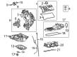
OEM Toyota Tundra Cylinder Head Gasket
Engine Cylinder Head Gasket- Select Vehicle by Model
- Select Vehicle by VIN
Select Vehicle by Model
orMake
Model
Year
Select Vehicle by VIN
For the most accurate results, select vehicle by your VIN (Vehicle Identification Number).
12 Cylinder Head Gaskets found


Toyota Tundra Gasket, Cylinder Head Part Number: 11116-38010
$66.23 MSRP: $92.97You Save: $26.74 (29%)Ships in 1-2 Business Days

Toyota Tundra Gasket, Cylinder Head Part Number: 11115-38021
$79.98 MSRP: $112.26You Save: $32.28 (29%)Ships in 1-3 Business Days


Toyota Tundra Head Gasket Part Number: 11116-31011
$81.16 MSRP: $113.92You Save: $32.76 (29%)Ships in 1-2 Business Days

Toyota Tundra Head Gasket Part Number: 11116-62081
$60.30 MSRP: $84.65You Save: $24.35 (29%)Ships in 1-3 Business Days

Toyota Tundra Head Gasket Part Number: 11115-62081
$65.64 MSRP: $92.13You Save: $26.49 (29%)Ships in 1-3 Business Days

Toyota Tundra Head Gasket Part Number: 11115-31031
$81.16 MSRP: $113.92You Save: $32.76 (29%)Ships in 1-2 Business Days
Toyota Tundra Gasket, Cylinder Head Part Number: 11116-50070
$99.88 MSRP: $140.20You Save: $40.32 (29%)Ships in 1-2 Business Days
Toyota Tundra Gasket, Cylinder Head Part Number: 11115-50080
$102.73 MSRP: $144.20You Save: $41.47 (29%)Ships in 1-2 Business Days
Toyota Tundra Head Gasket Part Number: 11115-31091
$65.99 MSRP: $92.63You Save: $26.64 (29%)Ships in 1-3 Business Days
Toyota Tundra Gasket, Cylinder Head, Driver Side Part Number: 11116-70011
$124.66 MSRP: $176.46You Save: $51.80 (30%)Ships in 1-2 Business Days
Toyota Tundra Head Gasket Part Number: 11116-31071
$58.42 MSRP: $81.32You Save: $22.90 (29%)Ships in 1-3 Business Days
Toyota Tundra Head Gasket, Passenger Side Part Number: 11115-70070
$111.50 MSRP: $156.50You Save: $45.00 (29%)Ships in 1-3 Business Days
Toyota Tundra Cylinder Head Gasket
Choose genuine Cylinder Head Gasket that pass strict quality control tests. You can trust the top quality and lasting durability. Shopping for OEM Cylinder Head Gasket for your Toyota Tundra? Our website is your one-stop destination. We stock an extensive selection of genuine Toyota Tundra parts. The price is affordable so you can save more. It only takes minutes to browse and find the exact fit. Easily add to cart and check out fast. Our hassle-free return policy will keep you stress-free. We process orders quickly for swift delivery. Your parts will arrive faster, so you can get back on the road sooner.
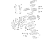
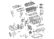
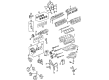
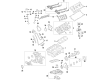
Cylinder Head Gasket is one of the components widely acknowledged for its dependability and durability to help maximize the reliability and safety of Toyota Tundra automobiles. This gasket suits perfectly to seal the engine and cylinder head from leakage of the combustion gases, coolant and oil crucial in ensuring the optimal performance and to avoid overheating of the engine. The Cylinder Head Gasket is one of a new generation of MLS - Multi Layer Steel - which is effective for the whole line of Tundra cars, including both the first and the second generation. Problems arising from Cylinder Head Gasket failure include loss of coolant and knocking, emphasising the need to service your Tundra. The Toyota Tundra has been recognized with awards such as the Motor Trend Truck of the Year and therefore, the part Cylinder Head Gasket is a crucial component in improving the reputation of the truck. Moreover, the Cylinder Head Gasket comes with the option of different engine sizes; 4.0 L V6 to the enhanced 5.7 L V8 guarantee that it meets the diverse demand of Tundra. Besides, its efficient design improves not only the performance of the engine but guarantees safety and durability of the overall vehicle, so, Cylinder Head Gasket is one of the optimal decisions on the auto market.
Toyota Tundra Cylinder Head Gasket Parts and Q&A
- Q: How to remove the Cylinder Head Gasket for Bank 2 on Toyota Tundra?A:Starting the replacement process of the Bank 2 Cylinder Head Gasket on a 1GR-FE engine requires engine assembly removal from the vehicle. During removal proceed by taking out the Ignition Coil assembly and Spark Plug together with the VVT sensor and Camshaft timing oil control valve assembly. The enclosed service begins with removal of right and left cylinder head cover sub-assemblies before removing the engine oil level dipstick guide followed by heater water pipe sub-assembly and rear water by-pass joint and oil control valve filter then progresses to V-ribbed belt tensioner assembly and No. 2 idler pulley sub-assembly and completes with No. 1 idler pulley sub-assembly. The technician should remove the crankshaft pulley followed by the No. 2 oil pan sub-assembly and then the oil strainer sub-assembly and ultimately the oil pan sub-assembly. Start the removal process by disconnecting the No. 2 oil cooler hose and the oil cooler hose followed by the water inlet housing and then the timing chain cover sub-assembly with the oil filter bracket sub-assembly. Set the No. 1 cylinder to TDC/compression position before removing the front crankshaft oil seal and subsequent components like the No. 1 chain tensioner assembly, chain tensioner slipper, No. 1 idle gear shaft, No. 2 chain vibration damper, No. 1 chain and No. 1 chain vibration damper and camshaft timing gears and No. 2 chain in correct order. Once done with the removal of both the No. 3 chain tensioner assembly and the No. 3 camshaft and No. 4 camshaft one must keep the camshaft level to avoid damages. Remove the bolt set from 16 bearing cap positions according to their specified sequence before taking out both 2 camshafts and 8 bearing caps. The left side cylinder head sub-assembly requires users to begin by evenly unsettling and extracting the 2 cylinder head bolts in their specified order before loosening the 8 cylinder head bolts in a set sequence using a 10 mm bi-hexagon wrench to remove both bolts together with plate washers while maintaining caution against washer drop into the cylinder head. Lift the cylinder head from its dowels on the cylinder block and set it on wooden blocks on the bench while keeping the contact surfaces undamaged. You may need to use a screwdriver lightly between the cylinder head and cylinder block when lifting if required. The gasket from the No. 2 cylinder head position should be removed.
- Q: How to install the cylinder head gasket on Toyota Tundra?A:For 1GR-FE engine cylinder head gasket installation start by stripping off existing packing materials (FIPG) then protect both cylinder head and cylinder block contact surfaces from oil damage. Place the new cylinder head gasket onto the cylinder block surface with the front face of the Lot No. stamp facing upward while the application time remains within 3 minutes using Toyota Genuine Seal Packing Black or Three Bond 1207B or equivalent material at a standard seal diameter between 2.5 and 3.0 mm (0.0984 to 0.118 in.). Keep the component free from engine oil during the following 2 hours. After the cylinder head sub-assembly RH is installed the work proceeds to the No. 1 and No. 2 Camshaft bearings while maintaining the camshaft in a level position to avoid damage during the installation. Position the crankshaft first before applying engine oil to thrust portions and camshaft journals of the camshafts. Place the camshafts onto the cylinder head with correct facing of the No. 1 cylinder lobes. Installation of the 8 bearing caps requires engine oil before placing them in correct positions followed by application of engine oil on the threads and under the heads of the 16 bearing cap bolts. These bolts need to be installed in weighted steps according to specified torque values: 9.0 Nm (92 kgf-cm, 80 in-lbf) for 10 mm head and 24 Nm (245 kgf-cm, 18 ft-lbf) for 12 mm head. Rotate the camshafts while facing clockwise until you reach 90 degrees with respect to the cylinder head for the camshaft knock pin alignment. The installation process requires the sequence of No. 2 chain tensioner assembly followed by camshaft timing gears and then No. 2 chain and chain tensioner slipper before adding the No. 1 chain tensioner assembly and No. 1 chain and No. 2 chain vibration damper then No. 1 idle gear shaft and front crankshaft oil seal with timing chain cover sub-assembly and oil filter bracket sub-assembly and water inlet housing and finally connecting oil cooler hoses. Proceed with the installation of the oil pan sub-assembly and oil strainer sub-assembly then the No. 2 oil pan sub-assembly followed by the cylinder head cover sub-assemblies RH and LH and the engine oil level dipstick guide. The rear water by-pass joint installation requires two new gaskets along with a new O-ring which must be lubricated with soapy water until securely tightened by two bolts and four nuts at 9.0 Nm (92 kgf-cm, 80 in-lbf). Afterward, attach the engine coolant temperature sensor connector. The heater water pipe sub-assembly should be installed and bolted to 9.8 Nm (100 kgf-cm, 87 in-lbf) while connecting all three water hoses. The procedure concludes with engine assembly installation to the vehicle after establishing the crankshaft pulley and the No. 1 and No. 2 idler pulley sub-assemblies and V-ribbed belt tensioner assembly, oil control valve filter, heater water pipe sub-assembly, Spark Plug, VVT sensor, camshaft timing oil control valve assembly and Ignition Coil assembly.


Related Toyota Tundra Parts
 Toyota Tundra Oil Filter
 Toyota Tundra Timing Belt
 Toyota Tundra Dipstick
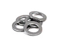 Toyota Tundra Oil Drain Plug Gasket
 Toyota Tundra Timing Chain Tensioner
 Toyota Tundra Crankshaft Gear
 Toyota Tundra Crankshaft Pulley
 Toyota Tundra Dipstick Tube
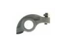 Toyota Tundra Rocker Arm
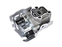 Toyota Tundra Spool Valve
 Toyota Tundra Timing Cover
 Toyota Tundra Valve Stem Seal