My Garage
Cart
Make sure this part fits

Toyota 11115-31031
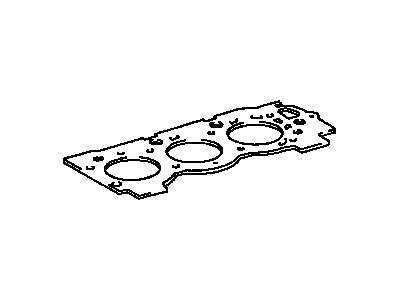
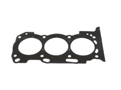
Head Gasket

2003-2015 Toyota 1111531031

Customer Questions & Expert Answers (9)
Toyota 11115-31031 Head Gasket
  • Part Description
    Gasket, Cylinder Head; Engine Cylinder Head Gasket; Cylinder Head Gasket; Engine Gasket Set
  • Part Name Code
    11115
  • Replaces
    11115-31030
  • Manufacturer
    Toyota
Make sure this part fits
$77.96 MSRP: $109.43
You Save: $31.47 (29%)
Ships in 1-2 Business Days
1
ADD TO CART
  • Related Parts
  • Product Specifications
  • Vehicle Fitment
  • Customer Questions & Expert Answers
  • Product Specifications

    BrandGenuine Toyota
    Part Name Code11115
    Manufacturer Part Number11115-31031
    Part DescriptionGasket, Cylinder Head; Engine Cylinder Head Gasket; Cylinder Head Gasket; Engine Gasket Set
    Item Dimensions25.5 x 9.5 x 0.1 inches
    Item Weight0.70 Pounds
    ConditionNew
    Fitment TypeDirect Replacement
    Replaces11115-31030
    ManufacturerToyota
    SKU11115-31031
    WarrantyThis genuine Toyota part is guaranteed by Toyota's factory warranty.
    Shipping & ReturnShipping Policy Return Policy
    Warning: California's Proposition 65
  • Vehicle Fitment

    Year Make Model Trim Engine
    2003-2009 Toyota 4RunnerLimited, Sport, SR56 Cyl 4.0 L GAS
    2007-2009 Toyota FJ CruiserBase, Trail Teams Special Edition, TRD Special Edition6 Cyl 4.0 L GAS
    2005-2015 Toyota TacomaBase, Pre Runner, TRD Pro, X-Runner6 Cyl 4.0 L GAS
    2005-2010 Toyota TundraBase, SR56 Cyl 4.0 L GAS
  • Customer Questions & Expert Answers

    Q:
    Is 11115-31031 a good match for my car? Posted by ToyotaPartsNow Specialist
    A:
    Find out if part number 11115-31031 is the right fit for your car by Selecting Your Vehicle model.
    Posted by ToyotaPartsNow Specialist
    Q:
    How to replace Cylinder Head Gasket No. 2 on Toyota 4Runner? Posted by Customer
    A:
    The first step for Cylinder Head Gasket No. 2 replacement involves stopping gasoline from leakage. Disassemble the chain sub-assembly and exhaust front pipe assembly No. 2 and manifold stay No. 2 using the removal of their respective 3 bolts. Begin by disconnecting the A/F sensor connector followed by removing 6 nuts that separate exhaust manifold from the gasket for taking out the exhaust manifold sub-assembly LH. Begin the body of work by disconnecting sub-assemblies No. 1 and No. 2 of the fuel pipes and then detach the intake manifold followed by water by-pass joint RR and finally chain vibration damper No. 1 through its 2 bolt removal. After pushing down chain tensioner No. 3 and inserting a 1.0 mm pin remove the camshaft timing gears together with timing chain No. 2 (LH bank) from the engine while the hexagonal portion of the camshaft must be held in place with a wrench to unfist the 2 bolts and timing gear assembly. Release chain tensioner assembly No. 3 before properly removing the camshafts with a method to maintain their horizontal position to prevent any damage. Uniform bolt removal from the 16 bearing cap results in extraction of the 8 bearing caps and 2 camshafts. Beginning with a ground cable separation and subsequent 2 cylinder head bolt loosening, proceed to remove the 8 cylinder head bolts in the correct order until the cylinder head can be lifted from the dowels onto wooden blocks. The cylinder head set bolt requires examination with a vernier caliper to ensure it meets the specifications of 10.85 - 11.00 mm standard outside diameter with 10.7 mm minimum. Install a new cylinder head gasket after cleaning old packing material and apply a continuous bead of seal packing (Part No. 08826-00080) within 3 minutes, placing the gasket in its appropriate position. Begin by placing the cylinder head gasket on its surface and then install the 8 cylinder head bolts with light engine oil on the threads before stepwise tightening to reach 36 Nm torque and front-side paint marking for each bolt before retightening them 180 degreres and installing the 2 additional cylinder head bolts at 30 Nm torque. The ground cable needs reinstalling with 8.0 Nm of torque. Install the camshafts in level position then set crankshaft correctly while applying new engine oil on the camshafts before installing the 8 bearing caps with 16 bearing cap bolts receiving specified torques based on head thickness. Following the installation of assembly No. 3 chain tensioner comes the installation of camshaft timing gears and No. 2 chain alternating the marks properly while tightening all bolts to 100 Nm. We need to install chain vibration damper No. 1 together with water by-pass joint RR and intake manifold and fuel pipe sub-assemblies No. 1 and No. 2. Mount the LH exhaust manifold assembly with its new gasket before securing the 6 nuts to 30 Nm torque specification followed by installing manifold stay No. 2 and its 3 bolts to 40 Nm torque. Then install the exhaust front pipe assembly No. 2 along with the chain sub-assembly. The last procedure includes inspecting fuel and exhaust gas leaks while using Special Service Tool: 09843-18030 to measure engine idle speed and evaluating CO/HC levels.
    Posted by ToyotaPartsNow Specialist
    Q:
    How to Remove the Cylinder Head Gasket on Toyota Tundra? Posted by Customer
    A:
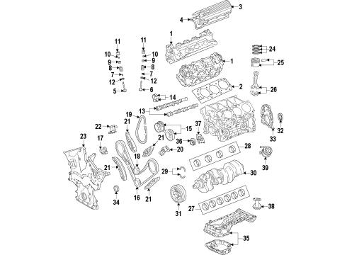
    The 1GR-FE engine cylinder head gasket removal starts by separating the engine assembly from its vehicle assembly. You must remove the ignition coil assembly followed by spark plug together with the VVT sensor and the camshaft timing oil control valve assembly. The maintenance procedure involves removing both right and left cylinder head cover sub-assemblies along with the engine oil level dipstick guide, heater water pipe sub-assembly, rear water by-pass joint, oil control valve filter and its components which include V-ribbed belt tensioner assembly, No. 2 idler pulley sub-assembly, No. 1 idler pulley sub-assembly, crankshaft pulley, No. 2 oil pan sub-assembly, oil strainer sub-assembly, and oil pan sub-assembly. The maintenance technician detaches the No. 2 oil cooler hose and the oil cooler hose before separating the water inlet housing and the oil filter bracket sub-assembly along with timing chain cover sub-assembly. The mechanic must execute the following steps: first remove the front crankshaft oil seal followed by setting No. 1 cylinder to TDC/compression then they must remove the No. 1 chain tensioner assembly, chain tensioner slipper, No. 1 idle gear shaft and all components including the No. 2 chain vibration damper, No. 1 chain, No. 1 chain vibration damper and camshaft timing gears and No. 2 chain. During the removal process maintain a level position of camshafts while removing both the No. 3 chain tensioner assembly and both the No. 3 camshaft and No. 4 camshaft. First step is to loosen then remove the 16 bearing cap bolts installed in proper sequence followed by extraction of 8 bearing caps and 2 camshafts. The left side cylinder head sub-assembly removal requires following these steps: loosening the 2 cylinder head bolts while removing the 8 cylinder head bolts with plate washers in order; then lifting the cylinder head from the dowels on the cylinder block by placing it on wooden blocks. Washers securing the contact surfaces must be handled with care while the No. 2 cylinder head gasket needs to be taken out.
    Posted by ToyotaPartsNow Specialist
    Q:
    How to install the cylinder head gasket on Toyota Tundra? Posted by Customer
    A:
    Installation of 1GR-FE cylinder head gaskets begins with removing old FIPG packing while preventing contact surfaces of the cylinder head and cylinder block from getting contaminated by oil. Seal Packing Black from Toyota Genuine should be applied to a new cylinder head gasket together with Three Bond 1207B or equivalent material with a standard seal diameter between 2.5 and 3.0 mm (0.0984 to 0.118 in.) before installing the gasket within three minutes of application while avoiding contact with engine oil for two hours post-installation. When installing the cylinder head gasket onto the cylinder block, put the front face of the Lot No. stamp upward while maintaining the correct installation orientation. The cylinder head sub-assembly RH installation should be followed by No. 1 and No. 2 camshaft bearings while also installing No. 1 and No. 2 camshafts with maintenance of camshaft level positioning to avoid damage during assembly. Place the components together with the No. 1 cylinder cam lobes facing correct directions while utilizing the crankshaft pulley set bolt for positioning and applying light engine oil on camshaft journals and thrust portions. After applying engine oil to the 8 bearing caps the technician should install them correctly before adding oil to the threads and under the heads of the 16 bearing cap bolts while following a specific torque sequence of 9.0 Nm (92 kgf-cm, 80 in-lbf) for 10 mm head bolts and 24 Nm (245 kgf-cm, 18 ft-lbf) for 12 mm head bolts. The mechanics will rotate the camshafts in a clockwise direction so the camshaft knock pin faces directly at a 90-degree angle toward the cylinder head. After installing the manifold front sub-assembly and connecting all oil cooler hoses, you should proceed with the installation of the No. 2 chain tensioner assembly, camshaft timing gears, No. 2 chain, chain tensioner slipper, No. 1 chain tensioner assembly, No. 1 chain, No. 2 chain vibration damper, No. 1 idle gear shaft, front crankshaft oil seal, timing chain cover sub-assembly, oil filter bracket sub-assembly, water inlet housing. The installation process starts with sub-assemblies of oil pan then oil strainer and finally No. 2 oil pan while finishing with cylinder head covers RH and LH as well as an engine oil level dipstick guide. When assembling the rear water bypass joint, install an O-ring on the water outlet pipe while setting new gaskets to water ports LH and RH. Apply soapy water on the O-ring before fastening the joint with 2 bolts and 4 nuts under 9.0 Nm (92 kgf-cm, 80 in-lbf), then connect the engine coolant temperature sensor. The heater water pipe sub-assembly requires 9.8 Nm (100 kgf-cm, 87 in-lbf) of torque for both bolts and the 3 water hoses need to be connected. After the engine assembly installation onto the vehicle the technician should install the crankshaft pulley and No. 1 and No. 2 idler pulley sub-assemblies as well as the V-ribbed belt tensioner assembly and oil control valve filter before connecting the heater water pipe sub-assembly and finishing up with the spark plug and VVT sensor and camshaft timing oil control valve assembly and ignition coil assembly installations.
    Posted by ToyotaPartsNow Specialist
    Q:
    How should the camshaft bearing No.2 be installed for the 2004 Toyota 4Runner? Posted by Customer
    A:
    Ensure cleanliness and install the camshafts while keeping them level, applying new engine oil to the thrust portion and journal.
    Posted by ToyotaPartsNow Specialist
    See expert answers on similar Cylinder Head Gasket
    Q:
    How do you install the camshafts for the 2003 Toyota 4Runner? Posted by Customer
    A:
    Install camshaft bearing No.2, then the camshafts while keeping them level, applying new engine oil, and tightening 16 bearing cap bolts to specified torque values.
    Posted by ToyotaPartsNow Specialist
    See expert answers on similar Cylinder Head Gasket
    Q:
    How quickly should the cylinder head be installed after applying seal packing for the 2004 Toyota 4Runner? Posted by Customer
    A:
    Install the cylinder head within 3 minutes and tighten the bolts within 15 minutes.
    Posted by ToyotaPartsNow Specialist
    See expert answers on similar Cylinder Head Gasket
    Q:
    What is the first step to remove the cylinder head gasket from the 1GR-FE engine for the 2009 Toyota Tundra? Posted by Customer
    A:
    First, remove the engine assembly from the vehicle.
    Posted by ToyotaPartsNow Specialist
    See expert answers on similar Cylinder Head Gasket
    Q:
    What is the next step regarding the crankshaft for the 2008 Toyota Tundra? Posted by Customer
    A:
    Remove the front crankshaft oil seal and set the No. 1 cylinder to TDC/compression.
    Posted by ToyotaPartsNow Specialist
    See expert answers on similar Cylinder Head Gasket
    If you have any questions about this product, please don't hesitate to ask us. We will be happy to help you!

OEM Toyota 11115-31031, Excellent Performance and Perfect Fitment

To ensure reliability, purchase Toyota part # 11115-31031 Head Gasket. It is sometimes referred to as Toyota Cylinder Head Gasket. OEM parts are unrivaled in terms of quality. They go through extensive quality control inspections and are produced in accordance with Toyota's official factory specifications. All of these remove defects and imperfections. So you can relax knowing they promise exceptional lifespan and flawless fitment.

ToyotaPartsNow.com is a leading supplier of genuine Toyota parts such as Toyota 1111531031 Head Gasket. At ToyotaPartsNow.com, we have a wide variety of OEM Toyota parts available at competitive prices. Our comprehensive range of genuine Toyota parts come with a manufacturer's warranty for peace of mind. We also prioritize customer satisfaction, providing a hassle-free return policy and expedited delivery for all our parts. For detailed Toyota parts information, click here.
Choose ToyotaPartsNow for discounted prices, exceptional service and fast delivery