×
ToyotaParts- Hello
- Login or Register
- Quick Links
- Live Chat
- Track Order
- Parts Availability
- RMA
- Help Center
- Contact Us
- Shop for
- Toyota Parts
- Scion Parts
My Garage
My Account
Cart
OEM Toyota Tundra ABS Control Module
Anti Lock Brake Control Module- Select Vehicle by Model
- Select Vehicle by VIN
Select Vehicle by Model
orMake
Model
Year
Select Vehicle by VIN
For the most accurate results, select vehicle by your VIN (Vehicle Identification Number).
58 ABS Control Modules found

Toyota Tundra Control Module Part Number: 44050-0C192
$902.88 MSRP: $1136.55You Save: $233.67 (21%)Ships in 1-3 Business Days
Toyota Tundra Modulator Valve Part Number: 44050-0C360
$816.39 MSRP: $1027.69You Save: $211.30 (21%)Ships in 1-3 Business DaysToyota Tundra Modulator Valve Part Number: 44050-0C340
$861.91 MSRP: $1084.98You Save: $223.07 (21%)Ships in 1-3 Business DaysToyota Tundra Actuator Assembly Part Number: 44050-AN011
$857.37 MSRP: $1079.26You Save: $221.89 (21%)Toyota Tundra Control Module Part Number: 44050-0C492
$895.84 MSRP: $1127.70You Save: $231.86 (21%)Ships in 1-3 Business DaysToyota Tundra Modulator Valve Part Number: 44050-0C610
$912.55 MSRP: $1148.73You Save: $236.18 (21%)Ships in 1-2 Business DaysToyota Tundra Actuator Assembly Part Number: 44050-AN031
$914.69 MSRP: $1151.41You Save: $236.72 (21%)Ships in 1-2 Business DaysToyota Tundra Control Module Part Number: 44050-0C502
$957.59 MSRP: $1205.42You Save: $247.83 (21%)Ships in 1-3 Business DaysToyota Tundra Control Module Part Number: 44050-0C420
$936.02 MSRP: $1178.27You Save: $242.25 (21%)Ships in 1-3 Business Days
Toyota Tundra Control Module Part Number: 44050-0C531
$971.21 MSRP: $1222.56You Save: $251.35 (21%)Ships in 1-3 Business DaysToyota Tundra Control Module Part Number: 44050-0C563
$956.68 MSRP: $1204.28You Save: $247.60 (21%)Ships in 1-3 Business DaysToyota Tundra Control Module Part Number: 44050-0C573
$1001.97 MSRP: $1261.28You Save: $259.31 (21%)Toyota Tundra Control Module Part Number: 44050-0C430
$992.32 MSRP: $1249.14You Save: $256.82 (21%)Ships in 1-3 Business DaysToyota Tundra Control Module Part Number: 44050-0C553
$1024.33 MSRP: $1289.43You Save: $265.10 (21%)Toyota Tundra Control Module Part Number: 44050-0C390
$1040.33 MSRP: $1309.57You Save: $269.24 (21%)Ships in 1-3 Business DaysToyota Tundra Actuator Assembly Part Number: 44050-0C330
$1046.23 MSRP: $1317.00You Save: $270.77 (21%)Ships in 1-3 Business DaysToyota Tundra Control Module Part Number: 44050-0C190
$1052.81 MSRP: $1325.29You Save: $272.48 (21%)Ships in 1-3 Business Days

Toyota Tundra Control Module Part Number: 44050-0C410
$1079.03 MSRP: $1358.29You Save: $279.26 (21%)

Toyota Tundra Modulator Valve Part Number: 44050-0C040


Toyota Tundra Modulator Valve Part Number: 44050-0C110
| Page 1 of 3 |Next >
1-20 of 58 Results
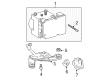
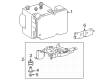
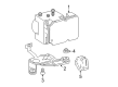
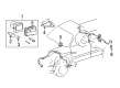
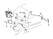
Toyota Tundra ABS Control Module
Choose genuine ABS Control Module that pass strict quality control tests. You can trust the top quality and lasting durability. Shopping for OEM ABS Control Module for your Toyota Tundra? Our website is your one-stop destination. We stock an extensive selection of genuine Toyota Tundra parts. The price is affordable so you can save more. It only takes minutes to browse and find the exact fit. Easily add to cart and check out fast. Our hassle-free return policy will keep you stress-free. We process orders quickly for swift delivery. Your parts will arrive faster, so you can get back on the road sooner.
A Toyota Tundra ABS Control Module is a critical part of the anti-lock braking system ABS identified with Toyota Tundra cars reputed for its sturdiness and efficiency. It greatly aids in the prevention of the wheels from locking up in the instance that the car experiences intense and prolonged braking making the control and safety of the car superior. The ABS Control Module is able to control the ABS modulator with help of inputs from wheel speed sensors to achieve optimal braking in different modes. Available for different Tundra vehicles, both with the first and second generation, the Toyota Tundra ABS Control Module is intended to work with the braking system of the car and enhance its performance. The modern technology that is in the ABS Control Module is the ESC and the traction control which enhance car stability and direction during sharp turns and any other instances that may lead to loss of control. Thus, using the case of the Tundra's ABS Control Module, it can also be understood how innovation is important to Toyota. The extended construction as well as the enhanced diagnostics options of the Toyota Tundra ABS Control Module creates a competitive advantage for automobiles in the market; the tundra's drivers can count on a safe and reliable SUV companion. In general, Toyota Tundra ABS Control Module reflects the company's commitment to the production of late models' vehicles and can be considered as essential for any Toyota Tundra driver who wants to feel more confident on the road.
Toyota Tundra ABS Control Module Parts and Q&A
- Q: How to install the ABS Control Module for Antilock Brakes on Toyota Tundra?A:The correct installation process for Hydraulic Control Assembly for Antilock Brakes starts with replacing the skid control ECU when needed then continuing with zero point calibrations of Steering Angle Sensor and master cylinder pressure sensor and yaw rate and deceleration sensor. The VSC actuator mounting requires 3 nuts for installation with the actuator bracket but do not drop the actuator because replacement is needed if it does drop. Follow the alphabet order to evenly torque the 3 nuts to 22 Nm (224 kgf-cm, 16 ft-lbf). Each Brake Line should receive its proper position on the brake actuator before union nut wrench usage to attach the 4 brake tubes while applying 15 Nm (155 kgf-cm, 11 ft-lbf) torque when using no wrench or 14 Nm (145 kgf-cm, 10 ft-lbf) torque when using the wrench with a proper wrench angle. Seam 2 brake tubes to the Brake Master Cylinder and another 2 tubes to the VSC actuator by applying the specified torque criteria. Once you connect the VSC actuator connector you can reconnect the battery cable to the negative terminal but system initialization might be needed afterward. A technician fills the brake reservoir, performs air bleeding on the brake master cylinder alongside brake lines and the VSC actuator assembly and checks the brake fluid amount in the reservoir. Check for any signs of brake fluid leakage before concluding the process.
- Q: How to remove and replace the ABS Control Module for Antilock Brakes on Toyota Tundra?A:The first step to remove and replace the Hydraulic Control Assembly for Antilock Brakes includes disconnecting the negative cable from the battery but requires waiting for 90 seconds following Ignition Switch deactivation to permit the system to save memory and set configuration. You must disconnect the VSC actuator connector through the pull of its release bar. Affix tags or note down the locations for reconnection before you disconnect the 2 brake tubes using a union nut wrench from the VSC actuator at the point where it meets the Brake Master Cylinder. Using the same union nut wrench disconnect the 4 brake tubes from the VSC actuator. Finish the VSC actuator removal using a 3-step process that involves the actuator bracket assembly removal after removing each of the 3 nuts.

Related Toyota Tundra Parts
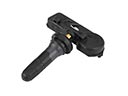 Toyota Tundra TPMS Sensor
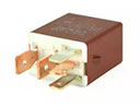 Toyota Tundra Fuel Pump Relay
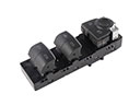 Toyota Tundra Power Window Switch
 Toyota Tundra Relay
 Toyota Tundra Speedometer
 Toyota Tundra Engine Control Module
 Toyota Tundra Cooling Fan Relay
 Toyota Tundra Dimmer Switch
 Toyota Tundra Hazard Warning Switch
 Toyota Tundra Mirror Switch
 Toyota Tundra Overload Relay
 Toyota Tundra Radiator Fan Relay
Browse Toyota Tundra ABS Control Module by Years
2025
2024
2023
2022
2021
2020
2019
2018
2017
2016
2015
2014
2013
2012
2011
2010
2009
2008
2007
2006
2005
2004
2003
2002
2001
2000