×
ToyotaParts- Hello
- Login or Register
- Quick Links
- Live Chat
- Track Order
- Parts Availability
- RMA
- Help Center
- Contact Us
- Shop for
- Toyota Parts
- Scion Parts
My Garage
My Account
Cart
OEM Toyota Solara Axle Shaft
Car Axle Shaft- Select Vehicle by Model
- Select Vehicle by VIN
Select Vehicle by Model
orMake
Model
Year
Select Vehicle by VIN
For the most accurate results, select vehicle by your VIN (Vehicle Identification Number).
29 Axle Shafts found

Toyota Solara Axle Assembly, Passenger Side Part Number: 43410-06480
$510.40 MSRP: $748.00You Save: $237.60 (32%)
Toyota Solara Axle Assembly, Driver Side Part Number: 43420-06490
$465.00 MSRP: $681.46You Save: $216.46 (32%)Ships in 1-3 Business Days
Toyota Solara Axle Assembly, Driver Side Part Number: 43420-06460
$397.00 MSRP: $581.80You Save: $184.80 (32%)Ships in 1-3 Business Days
Toyota Solara Axle Assembly, Driver Side Part Number: 43420-06450
$473.28 MSRP: $693.60You Save: $220.32 (32%)

Toyota Solara Axle Assembly, Passenger Side Part Number: 43410-06330
$465.83 MSRP: $682.68You Save: $216.85 (32%)Ships in 1-3 Business DaysToyota Solara Axle Assembly, Passenger Side Part Number: 43410-06460
$509.92 MSRP: $747.30You Save: $237.38 (32%)Ships in 1-3 Business Days
Toyota Solara Axle Assembly, Passenger Side Part Number: 43410-06252
$510.10 MSRP: $747.56You Save: $237.46 (32%)Ships in 1-3 Business DaysToyota Solara Axle Assembly, Passenger Side Part Number: 43410-06271
$531.40 MSRP: $778.76You Save: $247.36 (32%)Ships in 1-3 Business Days


Toyota Solara Axle Assembly, Driver Side Part Number: 43420-08010

Toyota Solara Axle Assembly, Passenger Side Part Number: 43410-06221
$510.40 MSRP: $748.00You Save: $237.60 (32%)Toyota Solara Axle Assembly, Driver Side Part Number: 43420-06320
Toyota Solara Axle Assembly, Driver Side Part Number: 43420-06281
Toyota Solara Axle Assembly, Driver Side Part Number: 43420-06280
Toyota Solara Axle Assembly, Driver Side Part Number: 43420-06271
Toyota Solara Axle Assembly, Driver Side Part Number: 43420-06270


Toyota Solara Axle Assembly, Driver Side Part Number: 43420-06060-84
Toyota Solara Axle Assembly, Driver Side Part Number: 43420-06050-84

Toyota Solara Reman Cv Axle, Right-Hand Part Number: 43410-06070-84
| Page 1 of 2 |Next >
1-20 of 29 Results
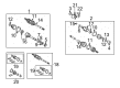
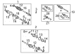
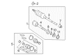
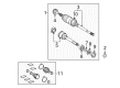
Toyota Solara Axle Shaft
Choose genuine Axle Shaft that pass strict quality control tests. You can trust the top quality and lasting durability. Shopping for OEM Axle Shaft for your Toyota Solara? Our website is your one-stop destination. We stock an extensive selection of genuine Toyota Solara parts. The price is affordable so you can save more. It only takes minutes to browse and find the exact fit. Easily add to cart and check out fast. Our hassle-free return policy will keep you stress-free. We process orders quickly for swift delivery. Your parts will arrive faster, so you can get back on the road sooner.
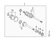
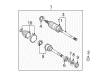
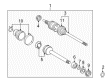
The Axle Shaft of Toyota Solara vehicles is an important component, which transmit torque from the differential system to the drive wheels to provide independent rotation, consequently increasing the tractive force. All these steel shafts are of different types including the solid axles for trucks and older cars and half shafts for the cars with independent suspension system. Differentials as well as axle shafts are established by solid axles, and half axles transmit force from the transaxle to the wheels. Each type can become worn with time and as such can cause noises, vibrations and possibly loss of lubricant. Axle shafts are crucial components to support the weight of the vehicle and transmit torque besides providing wheel alignment; thus, they are crucial for Toyota Solara automobiles.
Toyota Solara Axle Shaft Parts and Q&A
- Q: How to remove the axle shaft assembly on Toyota Solara?A:The front drive shaft assembly removal process starts with removing the engine under cover LH followed by draining manual transaxle oil by uninstalling the filler plug and gasket while also unattaching the drain plug and gasket. After this, secure two new gaskets with 49 Nm (500 kgf-cm, 36 ft. lbs.) torque. After draining automatic transaxle fluid through drain plug removal, users should replace the gasket along with the plug using identical torque values. Liberate the front wheel and front axle hub LH nut with Special Service Tool 09930-00010 and employ a hammer to unstake the nut to avoid damaging the drive shaft screw while ensuring its complete loosening. Lift off the stabilizer link assembly front piece LH by removing its securing nut then split the components while using a hexagon wrench (6 mm) if the Ball Joint starts to turn while unscrewing the nut. Users should peel apart the Speed Sensor front LH by disassembling its bolt and clip and pulling the wire and hose away from the Shock Absorber before unscrewing the bolt to split the sensor from the steering knuckle. Users must exercise care to avoid debris sticking to the sensor. The LH tie rod end subassembly requires first removing its cotter pin and nut before using Special Service Tool: 09628-62011 to disconnect it from the steering knuckle. Proceed to remove the front suspension arm subassembly lower No.1 LH by taking off its bolt and two nuts and disconnect the lower ball joint. A plastic hammer should be used to separate the front drive shaft assembly from the axle hub while you protect the drive shaft boot and speed sensor rotor from any damage. Detach the front drive shaft assembly LH using Special Service Tools 09520-01010 and 09520-24010 (09520-32040) while avoiding damage to the transaxle case oil seal inboard joint boot and drive shaft dust cover as well as maintaining control of the assembly. Remove the bearing bracket hole snap ring on the front drive shaft assembly RH by using a screwdriver before detaching the assembly from the drive shaft bearing bracket with its bolt. The front axle hub subassembly LH must be fixed using Special Service Tool: 09608-16042 (09608-02021, 09608-02041) because the hub bearing will suffer damage from the vehicle weight without this proper support.
- Q: How to install the Axle Shaft assembly LH and RH along with the associated components on Toyota Solara?A:When installing the front drive shaft assembly LH first coat the inboard joint shaft assembly spline with ATF before aligning the shaft splines through the use of a brass bar and hammer until the snap ring opens facing downward with the drive shaft assembly level to prevent damage to oil seal boot and dust cover. Insert new bearing bracket hole snap ring on the front drive shaft assembly RH with a screwdriver prior to torquing the bolt to 32 Nm (330 kgf-cm, 24 ft. lbs). The front axle assembly LH needs to be installed by fitting its drive shaft assembly LH while being cautious to prevent damage to boot joints and Speed Sensor rotors. Secure the lower Ball Joint of front suspension arm subassembly lower No.1 LH using a bolt together with 2 nuts which require 75 Nm (760 kgf-cm, 55 ft. lbs.) torque. For the installation of the tie rod end subassembly LH to the steering knuckle you need to use a nut and apply 49 Nm (500 kgf-cm, 36 ft. lbs.) of torque while adding a new cotter pin which should be tightened by an additional 60 degrees if the holes are not properly aligned. The front steering knuckle requires the speed sensor LH to attached with an 8.0 Nm (82 kgf-cm, 71 inch lbs.) torque while keeping the sensor clean from foreign matter. Subsequently install the flexible hose and speed sensor to the Shock Absorber using a bolt then set the knuckle sensor clip at 19 Nm (192 kgf-cm, 14 ft. lbs.) torque. This procedure needs to avoid both sensor wire twists and speed sensor damage. The front stabilizer link assembly LH needs to be installed with a nut that requires 74 Nm (755 kgf-cm, 55 ft. lbs.) torque while using a hexagon (6 mm) wrench on the stud for preventing the ball joint from rotating with the nut. Fasten the new axle hub LH nut into place with a 30 mm socket wrench until it reaches 294 Nm (3,000 kgf-cm, 217 ft. lbs.) torque level then use a chisel and hammer to stake the nut. The last step includes installing the front wheel with 103 Nm (1,050 kgf-cm, 76 ft. lbs.) torque before moving on to manual transaxle oil addition followed by checking the levels and automatic transaxle fluid inspection, front wheel alignment inspection and adjustment, and finally installing the engine under cover LH and verifying the ABS speed sensor signal.


Related Toyota Solara Parts
 Toyota Solara Control Arm Bushing
 Toyota Solara CV Boot
 Toyota Solara CV Joint
 Toyota Solara Front Cross-Member
 Toyota Solara Shock Absorber
 Toyota Solara Spare Wheel
 Toyota Solara Strut Mounts
 Toyota Solara Suspension Strut Rod
 Toyota Solara Sway Bar Bracket
 Toyota Solara Sway Bar Link
 Toyota Solara Transfer Case Output Shaft Snap Ring
 Toyota Solara Wheel Seal