×
ToyotaParts- Hello
- Login or Register
- Quick Links
- Live Chat
- Track Order
- Parts Availability
- RMA
- Help Center
- Contact Us
- Shop for
- Toyota Parts
- Scion Parts
My Garage
My Account
Cart
OEM Toyota Solara Shock Absorber
Suspension Shock Absorber- Select Vehicle by Model
- Select Vehicle by VIN
Select Vehicle by Model
orMake
Model
Year
Select Vehicle by VIN
For the most accurate results, select vehicle by your VIN (Vehicle Identification Number).
16 Shock Absorbers found

Toyota Solara Absorber Set, Front Right-Hand Part Number: 48510-80137
$140.05 MSRP: $198.25You Save: $58.20 (30%)Ships in 1-2 Business DaysToyota Solara Absorber Set, Front Left-Hand Part Number: 48520-39605
$126.42 MSRP: $178.96You Save: $52.54 (30%)Ships in 1 Business Day
Toyota Solara Strut, Rear Passenger Side Part Number: 48530-80142
$160.73 MSRP: $227.53You Save: $66.80 (30%)Ships in 1-3 Business Days
Toyota Solara Strut, Rear Driver Side Part Number: 48540-A9350
$126.07 MSRP: $178.46You Save: $52.39 (30%)Ships in 1-3 Business DaysToyota Solara Strut, Rear Passenger Side Part Number: 48530-A9670
$122.31 MSRP: $173.13You Save: $50.82 (30%)Ships in 1-3 Business DaysToyota Solara Strut, Rear Passenger Side Part Number: 48530-A9660
$136.64 MSRP: $193.43You Save: $56.79 (30%)Ships in 1-3 Business DaysToyota Solara Strut, Rear Driver Side Part Number: 48540-A9340
$139.11 MSRP: $196.92You Save: $57.81 (30%)Ships in 1-3 Business DaysToyota Solara Strut, Rear Driver Side Part Number: 48540-09840
$139.11 MSRP: $196.92You Save: $57.81 (30%)Ships in 1-3 Business DaysToyota Solara Strut, Rear Passenger Side Part Number: 48530-A9610
$158.61 MSRP: $224.54You Save: $65.93 (30%)Ships in 1-3 Business DaysToyota Solara Absorber Set, Rear Left-Hand Part Number: 48540-39565
$159.20 MSRP: $225.37You Save: $66.17 (30%)Ships in 1-3 Business DaysToyota Solara Strut, Rear Driver Side Part Number: 48540-A9290
$159.91 MSRP: $226.36You Save: $66.45 (30%)Ships in 1-3 Business DaysToyota Solara Strut, Rear Driver Side Part Number: 48540-A9280
$166.37 MSRP: $235.51You Save: $69.14 (30%)Ships in 1-3 Business DaysToyota Solara Strut, Rear Passenger Side Part Number: 48530-A9230
$166.37 MSRP: $235.51You Save: $69.14 (30%)Ships in 1-3 Business DaysToyota Solara Strut, Rear Passenger Side Part Number: 48530-09P30
Toyota Solara Strut, Rear Driver Side Part Number: 48540-A9260
Toyota Solara Strut, Rear Passenger Side Part Number: 48530-A9600
Toyota Solara Shock Absorber
Choose genuine Shock Absorber that pass strict quality control tests. You can trust the top quality and lasting durability. Shopping for OEM Shock Absorber for your Toyota Solara? Our website is your one-stop destination. We stock an extensive selection of genuine Toyota Solara parts. The price is affordable so you can save more. It only takes minutes to browse and find the exact fit. Easily add to cart and check out fast. Our hassle-free return policy will keep you stress-free. We process orders quickly for swift delivery. Your parts will arrive faster, so you can get back on the road sooner.
Toyota Solara Shock Absorber Parts and Q&A
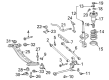
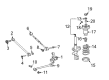
- Q: How to install the rear shock absorber assembly LH on Toyota Solara?A:The process to install the rear shock absorber assembly LH begins with attaching the spring bumper along with the insulator lower. The installation requires Special Service Tool: 09727-30021 to compress the coil spring while eliminating the use of an impact wrench to protect the tool from damage. Follow this step by fitting the lower end section of the coil spring into the lower seat gap then position the piston rod flat faces parallel with the LH support suspension flat faces. Insert the LH support suspension against the shock absorber lower bracket so the protruding section faces outward before clamping the collar to the piston rod and tightening a new nut which allows removal of Special Service Tool: 09727-30021 while checking the LH suspension alignment. Install the 3 upper rear shock absorber with coil spring nuts provisionally then torque them starting from 1 through 3 to reach 39 Nm (398 kgf-cm, 29 ft-lbf). Connect both shock absorber with coil spring bolts and nuts at 180 Nm torque rating (1,840 kgf-cm, 133 ft-lbf) while omitting top nut torque until resetting values for entire procedure completion. Fitting begins with the rear suspension support No.1 cover LH followed by rear LH flexible hose attachment alongside skid control sensor wire using 2 bolts tightened to a sequence of Bolt A at 19 Nm (195 kgf-cm, 14 ft-lbf) and Bolt B at 5.5 Nm (56 kgf-cm, 49 in-lbf). You should attach the rear stabilizer link assembly LH to the shock absorber using a nut then tighten it to 39 Nm (400 kgf-cm, 29 ft-lbf). Before doing so check if the Ball Joint moves freely with the nut. Use a 5 mm hexagon wrench to stabilize the stud when necessary. To finish the procedure install the rear wheel using 103 Nm of torque (1,050 kgf-cm / 76 ft-lbf) then check the rear wheel alignment.
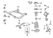
- Q: How to remove the rear shock absorber on Toyota Solara?A:You begin the procedure to remove the rear shock absorber by taking off the roof side garnish assembly inner RH and LH for the coupe body along with the package tray trim panel assembly. Begin by disconnecting the LH 3 point type belt assembly for the seat while proceeding to take out the convertible body type components that include the rear seat cushion assembly alongside the headrest plate cover and headrest assembly and shoulder belt cover. The removal process starts with taking out the rear seatback assembly followed by eliminating the quarter trim panel sub-assembly upper LH. A jack must support the rear axle carrier while you remove the rear stabilizer link assembly LH by unscrewing its nut and disconnecting it from the shock absorber through the use of a hexagon wrench (5 mm) to prevent the ball joint from rotating with the nut. The procedure to remove the rear LH flexible hose begins by taking out the 2 bolts and disconnecting it while detaching the skid control sensor wire attached to the shock absorber. The method to remove the rear shock absorber assembly involves loosening the 2 lower side nuts without removing the 2 bolts and 2 nuts followed by removing the rear suspension support No. 1 cover LH and loosening the LH support suspension center nut which remains in place. Put the 3 nuts aside before lowering the rear axle carrier and extracting the shock absorber with coil spring by removing its 2 nuts and 2 bolts positioned on the lower side.

Related Toyota Solara Parts
 Toyota Solara Ball Joint
 Toyota Solara Bump Stop
 Toyota Solara Coil Spring Insulator
 Toyota Solara Control Arm Bushing
 Toyota Solara Front Cross-Member
 Toyota Solara Steering Knuckle
 Toyota Solara Strut Housing
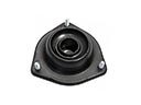 Toyota Solara Strut Mounts
 Toyota Solara Suspension Strut Rod
 Toyota Solara Sway Bar Bracket
 Toyota Solara Sway Bar Bushing
 Toyota Solara Sway Bar Link