×
ToyotaParts- Hello
- Login or Register
- Quick Links
- Live Chat
- Track Order
- Parts Availability
- RMA
- Help Center
- Contact Us
- Shop for
- Toyota Parts
- Scion Parts
My Garage
My Account
Cart
OEM 2007 Toyota Solara Axle Shaft
Car Axle Shaft- Select Vehicle by Model
- Select Vehicle by VIN
Select Vehicle by Model
orMake
Model
Year
Select Vehicle by VIN
For the most accurate results, select vehicle by your VIN (Vehicle Identification Number).
6 Axle Shafts found

2007 Toyota Solara Axle Assembly, Passenger Side
Part Number: 43410-06460$509.92 MSRP: $747.30You Save: $237.38 (32%)Ships in 1-3 Business DaysProduct Specifications- Other Name: Shaft Assembly, Front Drive; CV Axle Assembly, Front Right; GSP Cv Axle; Axle Shaft; Shaft Assembly, Front Drive, Passenger Side; CV Axle Assembly
- Position: Passenger Side
- Part Name Code: 43410
- Item Weight: 14.60 Pounds
- Item Dimensions: 30.1 x 7.4 x 6.6 inches
- Condition: New
- Fitment Type: Direct Replacement
- SKU: 43410-06460
- Warranty: This genuine part is guaranteed by Toyota's factory warranty.

2007 Toyota Solara Axle Assembly, Driver Side
Part Number: 43420-06490$465.00 MSRP: $681.46You Save: $216.46 (32%)Ships in 1-3 Business DaysProduct Specifications- Other Name: Shaft Assembly, Front Drive; CV Axle Assembly, Front Left; GSP Cv Axle; Axle Shaft; Shaft Assembly, Front Drive, Driver Side; CV Axle Assembly
- Manufacturer Note: W(ABS)
- Position: Driver Side
- Replaces: 43420-06221
- Part Name Code: 43420
- Item Weight: 7.30 Pounds
- Item Dimensions: 10.0 x 5.3 x 5.3 inches
- Condition: New
- Fitment Type: Direct Replacement
- SKU: 43420-06490
- Warranty: This genuine part is guaranteed by Toyota's factory warranty.
2007 Toyota Solara Axle Assembly, Driver Side
Part Number: 43420-06460$397.00 MSRP: $581.80You Save: $184.80 (32%)Ships in 1-3 Business DaysProduct Specifications- Other Name: Shaft Assembly, Front Drive; CV Axle Assembly, Front Left; GSP Cv Axle; Axle Shaft; Shaft Assembly, Front Drive, Driver Side; CV Axle Assembly
- Position: Driver Side
- Part Name Code: 43420
- Item Weight: 15.10 Pounds
- Item Dimensions: 28.9 x 7.4 x 6.4 inches
- Condition: New
- Fitment Type: Direct Replacement
- SKU: 43420-06460
- Warranty: This genuine part is guaranteed by Toyota's factory warranty.

2007 Toyota Solara Axle Assembly, Driver Side
Part Number: 43420-06450$459.44 MSRP: $673.30You Save: $213.86 (32%)Product Specifications- Other Name: Shaft Assembly, Front Drive; CV Axle Assembly, Front Left; GSP Cv Axle; Axle Shaft; Shaft Assembly, Front Drive, Driver Side; CV Axle Assembly
- Position: Driver Side
- Part Name Code: 43420
- Item Weight: 19.90 Pounds
- Item Dimensions: 29.8 x 5.3 x 5.2 inches
- Condition: New
- Fitment Type: Direct Replacement
- SKU: 43420-06450
- Warranty: This genuine part is guaranteed by Toyota's factory warranty.

2007 Toyota Solara Axle Assembly, Passenger Side
Part Number: 43410-06480$510.40 MSRP: $748.00You Save: $237.60 (32%)Product Specifications- Other Name: Shaft Assembly, Front Drive; CV Axle Assembly, Front Right; GSP Cv Axle; Axle Shaft; Shaft Assembly, Front Drive, Passenger Side; CV Axle Assembly
- Position: Passenger Side
- Part Name Code: 43410
- Item Weight: 25.20 Pounds
- Item Dimensions: 44.5 x 5.5 x 5.4 inches
- Condition: New
- Fitment Type: Direct Replacement
- SKU: 43410-06480
- Warranty: This genuine part is guaranteed by Toyota's factory warranty.

2007 Toyota Solara Axle Assembly, Passenger Side
Part Number: 43410-06221$510.40 MSRP: $748.00You Save: $237.60 (32%)Product Specifications- Other Name: Shaft Assembly, Front Drive; CV Axle Assembly, Front Right; GSP Cv Axle; Axle Shaft; Shaft Assembly, Front Drive, Passenger Side; CV Axle Assembly
- Manufacturer Note: W(ABS)
- Position: Passenger Side
- Part Name Code: 43410
- Item Weight: 15.30 Pounds
- Item Dimensions: 29.2 x 7.3 x 6.4 inches
- Condition: New
- Fitment Type: Direct Replacement
- SKU: 43410-06221
- Warranty: This genuine part is guaranteed by Toyota's factory warranty.
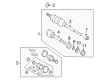
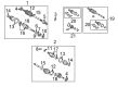
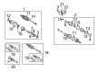
2007 Toyota Solara Axle Shaft
Looking for affordable OEM 2007 Toyota Solara Axle Shaft? Explore our comprehensive catalogue of genuine 2007 Toyota Solara Axle Shaft. All our parts are covered by the manufacturer's warranty. Plus, our straightforward return policy and speedy delivery service ensure an unparalleled shopping experience. We look forward to your visit!
2007 Toyota Solara Axle Shaft Parts Q&A
- Q: How to inspect the axle shaft on 2007 Toyota Solara?A: The inspection of the front drive shaft starts with examining radial play in the outboard joint. Check whether the inboard joint moves with minimal resistance in thrust motion and ignore any notable radial movement in the inboard joint. The boot inspection should include a check for damage while measuring the distance denoted as (A) in the drawn illustration. The procedure requires specific part numbers consisting of 3MZ-FE and two versions of 2AZ-FE (part 1 and part 2).
Related 2007 Toyota Solara Parts
 2007 Toyota Solara Ball Joint
 2007 Toyota Solara CV Boot
 2007 Toyota Solara CV Joint
 2007 Toyota Solara Coil Springs
 2007 Toyota Solara Control Arm
 2007 Toyota Solara Front Cross-Member
 2007 Toyota Solara Rear Crossmember
 2007 Toyota Solara Shock Absorber
 2007 Toyota Solara Sway Bar Bracket
 2007 Toyota Solara Sway Bar Bushing
 2007 Toyota Solara Sway Bar Link
 2007 Toyota Solara Transfer Case Output Shaft Snap Ring