×
ToyotaParts- Hello
- Login or Register
- Quick Links
- Live Chat
- Track Order
- Parts Availability
- RMA
- Help Center
- Contact Us
- Shop for
- Toyota Parts
- Scion Parts
My Garage
My Account
Cart
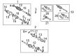
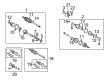
OEM 2008 Toyota Solara Axle Shaft
Car Axle Shaft- Select Vehicle by Model
- Select Vehicle by VIN
Select Vehicle by Model
orMake
Model
Year
Select Vehicle by VIN
For the most accurate results, select vehicle by your VIN (Vehicle Identification Number).
6 Axle Shafts found

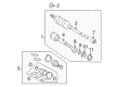
2008 Toyota Solara Axle Assembly, Passenger Side
Part Number: 43410-06460$509.92 MSRP: $747.30You Save: $237.38 (32%)Ships in 1-3 Business DaysProduct Specifications- Other Name: Shaft Assembly, Front Drive; CV Axle Assembly, Front Right; GSP Cv Axle; Axle Shaft; Shaft Assembly, Front Drive, Passenger Side; CV Axle Assembly
- Position: Passenger Side
- Part Name Code: 43410
- Item Weight: 14.60 Pounds
- Item Dimensions: 30.1 x 7.4 x 6.6 inches
- Condition: New
- Fitment Type: Direct Replacement
- SKU: 43410-06460
- Warranty: This genuine part is guaranteed by Toyota's factory warranty.

2008 Toyota Solara Axle Assembly, Driver Side
Part Number: 43420-06490$465.00 MSRP: $681.46You Save: $216.46 (32%)Ships in 1-3 Business DaysProduct Specifications- Other Name: Shaft Assembly, Front Drive; CV Axle Assembly, Front Left; GSP Cv Axle; Axle Shaft; Shaft Assembly, Front Drive, Driver Side; CV Axle Assembly
- Manufacturer Note: W(ABS)
- Position: Driver Side
- Replaces: 43420-06221
- Part Name Code: 43420
- Item Weight: 7.30 Pounds
- Item Dimensions: 10.0 x 5.3 x 5.3 inches
- Condition: New
- Fitment Type: Direct Replacement
- SKU: 43420-06490
- Warranty: This genuine part is guaranteed by Toyota's factory warranty.
2008 Toyota Solara Axle Assembly, Driver Side
Part Number: 43420-06460$397.00 MSRP: $581.80You Save: $184.80 (32%)Ships in 1-3 Business DaysProduct Specifications- Other Name: Shaft Assembly, Front Drive; CV Axle Assembly, Front Left; GSP Cv Axle; Axle Shaft; Shaft Assembly, Front Drive, Driver Side; CV Axle Assembly
- Position: Driver Side
- Part Name Code: 43420
- Item Weight: 15.10 Pounds
- Item Dimensions: 28.9 x 7.4 x 6.4 inches
- Condition: New
- Fitment Type: Direct Replacement
- SKU: 43420-06460
- Warranty: This genuine part is guaranteed by Toyota's factory warranty.

2008 Toyota Solara Axle Assembly, Driver Side
Part Number: 43420-06450$459.44 MSRP: $673.30You Save: $213.86 (32%)Product Specifications- Other Name: Shaft Assembly, Front Drive; CV Axle Assembly, Front Left; GSP Cv Axle; Axle Shaft; Shaft Assembly, Front Drive, Driver Side; CV Axle Assembly
- Position: Driver Side
- Part Name Code: 43420
- Item Weight: 19.90 Pounds
- Item Dimensions: 29.8 x 5.3 x 5.2 inches
- Condition: New
- Fitment Type: Direct Replacement
- SKU: 43420-06450
- Warranty: This genuine part is guaranteed by Toyota's factory warranty.

2008 Toyota Solara Axle Assembly, Passenger Side
Part Number: 43410-06480$510.40 MSRP: $748.00You Save: $237.60 (32%)Product Specifications- Other Name: Shaft Assembly, Front Drive; CV Axle Assembly, Front Right; GSP Cv Axle; Axle Shaft; Shaft Assembly, Front Drive, Passenger Side; CV Axle Assembly
- Position: Passenger Side
- Part Name Code: 43410
- Item Weight: 25.20 Pounds
- Item Dimensions: 44.5 x 5.5 x 5.4 inches
- Condition: New
- Fitment Type: Direct Replacement
- SKU: 43410-06480
- Warranty: This genuine part is guaranteed by Toyota's factory warranty.

2008 Toyota Solara Axle Assembly, Passenger Side
Part Number: 43410-06221$510.40 MSRP: $748.00You Save: $237.60 (32%)Product Specifications- Other Name: Shaft Assembly, Front Drive; CV Axle Assembly, Front Right; GSP Cv Axle; Axle Shaft; Shaft Assembly, Front Drive, Passenger Side; CV Axle Assembly
- Manufacturer Note: W(ABS)
- Position: Passenger Side
- Part Name Code: 43410
- Item Weight: 15.30 Pounds
- Item Dimensions: 29.2 x 7.3 x 6.4 inches
- Condition: New
- Fitment Type: Direct Replacement
- SKU: 43410-06221
- Warranty: This genuine part is guaranteed by Toyota's factory warranty.
2008 Toyota Solara Axle Shaft
Looking for affordable OEM 2008 Toyota Solara Axle Shaft? Explore our comprehensive catalogue of genuine 2008 Toyota Solara Axle Shaft. All our parts are covered by the manufacturer's warranty. Plus, our straightforward return policy and speedy delivery service ensure an unparalleled shopping experience. We look forward to your visit!
2008 Toyota Solara Axle Shaft Parts Q&A
- Q: How to remove the axle shaft assembly on 2008 Toyota Solara?A: The procedure to remove the front drive shaft assembly starts with removing the engine under cover on the LH side while draining manual transaxle oil and automatic transaxle fluid for U151E and U250E. First untie the front axle shaft LH nut using Special Service Tool: 09930-00010 and a hammer before using the tool to unstake the nut completely because the drive shaft screw can be damaged by excessive torque. First apply the vehicle brakes before taking off the lock axle hub LH nut. remove the front stabilizer link assembly by first unstowing the link nut to detach it while using a 6 mm hexagon wrench for steady support to the ball joint stud. Use a suitable tool to dismount the speed sensor front LH by deslating its bolt and adjacent clip before fully removing it from the steering knuckle. Move to separate the tie rod end sub-assembly LH by using the Special Service Tool: 09628-62011 to remove its nut and cotter pin when detaching from the steering knuckle. To detach the front suspension arm sub-assembly lower No.1 LH the technician must remove its lower ball joint bolt and two attached nuts. A plastic hammer should be used to separate the front drive shaft assembly from the axle hub but drivers must protect the drive shaft boot and speed sensor rotor from damage during this process. Lift off the front drive shaft assembly LH with Special Service Tool: 09520-01010, 09520-24010, 09520-32040 taking care to safeguard transaxle case oil seal and inboard joint boot and drive shaft dust cover and preventing any drive shaft drop. The front drive shaft assembly RH requires removal of its bearing bracket hole snap ring with a screwdriver before disconnection of the bolt to extract the assembly from the drive shaft bearing bracket. Complete the installation of front axle hub sub-assembly LH by using specific service tools 09608-02021, 09608-16042, and 09608-02041. Heavy vehicle weight can harm the bearing if it is not properly supported during installation.
Related 2008 Toyota Solara Parts
 2008 Toyota Solara Ball Joint
 2008 Toyota Solara CV Boot
 2008 Toyota Solara Coil Springs
 2008 Toyota Solara Control Arm
 2008 Toyota Solara Crossmember Bushing
 2008 Toyota Solara Front Cross-Member
 2008 Toyota Solara Rear Crossmember
 2008 Toyota Solara Shock Absorber
 2008 Toyota Solara Sway Bar Bracket
 2008 Toyota Solara Sway Bar Bushing
 2008 Toyota Solara Sway Bar Link
 2008 Toyota Solara Transfer Case Output Shaft Snap Ring