×
ToyotaParts- Hello
- Login or Register
- Quick Links
- Live Chat
- Track Order
- Parts Availability
- RMA
- Help Center
- Contact Us
- Shop for
- Toyota Parts
- Scion Parts
My Garage
My Account
Cart
OEM 2000 Toyota Solara Axle Shaft
Car Axle Shaft- Select Vehicle by Model
- Select Vehicle by VIN
Select Vehicle by Model
orMake
Model
Year
Select Vehicle by VIN
For the most accurate results, select vehicle by your VIN (Vehicle Identification Number).
8 Axle Shafts found

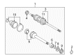 Product Specifications
- Other Name: REMAN CV AXLE, RH; CV Axle Assembly; Axle Shaft
- Position: Passenger Side
- Item Weight: 14.50 Pounds
- Item Dimensions: 31.0 x 5.3 x 5.4 inches
- Condition: New
- SKU: 43410-06070-84
- Warranty: This genuine part is guaranteed by Toyota's factory warranty.

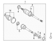 Product Specifications
- Other Name: Reman Cv Axle, Left-Hand; CV Axle Assembly, Front Left; CV Axle Assembly; GSP Cv Axle; Axle Shaft
- Position: Driver Side
- Item Weight: 14.90 Pounds
- Item Dimensions: 8.6 x 4.3 x 4.2 inches
- Condition: New
- SKU: 43420-06060-84
- Warranty: This genuine part is guaranteed by Toyota's factory warranty.
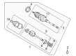
- Product Specifications
- Other Name: REMAN CV AXLE, LH; CV Axle Assembly; Axle Shaft
- Position: Driver Side
- Replaces: 43420-06070
- Item Weight: 14.50 Pounds
- Item Dimensions: 32.2 x 5.3 x 5.4 inches
- Condition: New
- SKU: 43420-06070-84
- Warranty: This genuine part is guaranteed by Toyota's factory warranty.
- Product Specifications
- Other Name: Reman Cv Axle, Right-Hand; CV Axle Assembly, Front Right; CV Axle Assembly; GSP Cv Axle; Axle Shaft
- Position: Passenger Side
- Item Weight: 14.00 Pounds
- Item Dimensions: 30.7 x 7.5 x 6.6 inches
- Condition: New
- SKU: 43410-06060-84
- Warranty: This genuine part is guaranteed by Toyota's factory warranty.
- Product Specifications
- Other Name: Reman Cv Axle, Left-Hand; CV Axle Assembly, Front Left; CV Axle Assembly; GSP Cv Axle; Axle Shaft
- Position: Driver Side
- Item Weight: 14.40 Pounds
- Item Dimensions: 31.0 x 7.8 x 6.7 inches
- Condition: New
- SKU: 43420-06050-84
- Warranty: This genuine part is guaranteed by Toyota's factory warranty.

 Product Specifications
- Other Name: Reman Cv Axle, Right-Hand; CV Axle Assembly, Front Right; CV Axle Assembly; GSP Cv Axle; Axle Shaft
- Position: Passenger Side
- Item Weight: 22.00 Pounds
- Item Dimensions: 30.4 x 7.8 x 6.6 inches
- Condition: New
- SKU: 43410-06050-84
- Warranty: This genuine part is guaranteed by Toyota's factory warranty.
- Product Specifications
- Other Name: Shaft Assembly, Front Drive; CV Axle Assembly, Front Left, Front Right; GSP Cv Axle; Axle Shaft; Shaft Assembly, Front Drive, Passenger Side; CV Axle Assembly
- Position: Passenger Side
- Replaces: 43410-06100, 43410-06030, 43410-06040, 43410-06090
- Part Name Code: 43410
- Item Weight: 14.60 Pounds
- Item Dimensions: 31.3 x 8.0 x 6.7 inches
- Condition: New
- Fitment Type: Direct Replacement
- SKU: 43410-06180
- Warranty: This genuine part is guaranteed by Toyota's factory warranty.
- Product Specifications
- Other Name: Shaft Assembly, Front Drive; CV Axle Assembly, Front Left; GSP Cv Axle; Axle Shaft; Shaft Assembly, Front Drive, Driver Side; CV Axle Assembly
- Position: Driver Side
- Replaces: 43420-06040, 43420-06030, 43420-06100, 43420-06090
- Part Name Code: 43420
- Item Weight: 20.70 Pounds
- Item Dimensions: 30.4 x 7.8 x 6.7 inches
- Condition: New
- Fitment Type: Direct Replacement
- SKU: 43420-06180
- Warranty: This genuine part is guaranteed by Toyota's factory warranty.
2000 Toyota Solara Axle Shaft
Looking for affordable OEM 2000 Toyota Solara Axle Shaft? Explore our comprehensive catalogue of genuine 2000 Toyota Solara Axle Shaft. All our parts are covered by the manufacturer's warranty. Plus, our straightforward return policy and speedy delivery service ensure an unparalleled shopping experience. We look forward to your visit!
2000 Toyota Solara Axle Shaft Parts Q&A
- Q: How to service and repair the axle shaft on 2000 Toyota Solara?A: Start the axle shaft service by evaluating drive shaft outboard joint play as well as inboard joint movement in thrust direction along with no radial play. Inspect the boots for damage. The inboard and outboard joint boot clamps need removal by first pinching the large inboard joint boot clamp with pliers followed by cutting the small inboard joint boot clamp and the two outboard joint boot clamps with a side cutter. An unforced procedure expands the snap ring as you apply the snap ring expander to remove the outboard joint shaft. Use a screwdriver along with a hammer device to remove the inboard joint shaft dust cover of the left-hand drive shaft. Laboratories should remove the transaxle side dust cover of the RH drive shaft by pressing it against the press fixture. Then use Special Service Tool: 09950-00020 and press to separate the bearing side dust cover from the snap ring and bearing before taking out the snap ring from the press procedure. The outboard joint shaft must be mounted within a soft jaw vise before removing the No. 2 dust deflector using both screwdriver and hammer techniques while preserving the ABS speed sensor rotor. Use the combination of Special Service Tools 09309-36010, 09316-20011 and press equipment to install a new No. 2 dust deflector. Proceed with constructing the RH drive shaft through snap ring application to the inboard joint shaft followed by using Special Service Tool: 09223-56010 and a press to install a new bearing along with new snap ring and bearing side and transaxle side dust covers. Verify that the specified value matches the inboard joint shaft tip to dust cover distance. The LH drive shaft receives its new dust cover installation through the combination of Special Service Tools: 09223-56010, 09555-55010 along with a press tool. Load the outboard and inboard joint boots together with their boot clamps as temporary fitment before applying vinyl tape around outboard joint shaft splines to avoid damage. Place the matchmarks into alignment before installing the inboard joint shaft into the outboard joint shaft with the help of a snap ring expander. The outboard joint and boot require 105 - 125 g of black grease before installing the boot while the inboard joint and boot need gray grease of the same amount for installation. Both boots need to sit properly within the groove of the shaft while the drive shaft maintains standard length. Apply the inboard boot clamp by positioning it while clamping A and B to activate C and G. After securing the clamp over both boots install Service Tool 09521-24010 over the clamp and restrict tool 09240-00020 from overtightening. Adjust the clamp clearance to reach the following values: A must be below 1.9 mm (0.075 inch) and B spans 1.5 to 2.5 mm (0.059 to 0.098 inch) and C exists from 3.0 to 4.0 mm (0.118 to 0.157 inch). Finally, check the drive shaft.
Related 2000 Toyota Solara Parts
 2000 Toyota Solara Ball Joint
 2000 Toyota Solara CV Boot
 2000 Toyota Solara CV Joint
 2000 Toyota Solara Coil Springs
 2000 Toyota Solara Control Arm
 2000 Toyota Solara Control Arm Bushing
 2000 Toyota Solara Front Cross-Member
 2000 Toyota Solara Rear Crossmember
 2000 Toyota Solara Shock Absorber
 2000 Toyota Solara Sway Bar Bushing
 2000 Toyota Solara Transfer Case Output Shaft Snap Ring
 2000 Toyota Solara Wheel Seal