×
ToyotaParts- Hello
- Login or Register
- Quick Links
- Live Chat
- Track Order
- Parts Availability
- RMA
- Help Center
- Contact Us
- Shop for
- Toyota Parts
- Scion Parts
My Garage
My Account
Cart
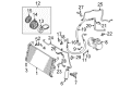
OEM Toyota Solara A/C Clutch
Air Conditioning Clutch- Select Vehicle by Model
- Select Vehicle by VIN
Select Vehicle by Model
orMake
Model
Year
Select Vehicle by VIN
For the most accurate results, select vehicle by your VIN (Vehicle Identification Number).
13 A/C Clutches found


Toyota Solara Hub Sub-Assembly, Magnet Clutch
Part Number: 88403-32010$133.43 MSRP: $188.90You Save: $55.47 (30%)Ships in 1-3 Business Days
Toyota Solara Clutch & Pulley
Part Number: 88410-42040$186.62 MSRP: $266.45You Save: $79.83 (30%)Ships in 1-2 Business Days
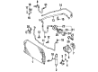
Toyota Solara Clutch Assembly, Magnet
Part Number: 88410-33040$140.28 MSRP: $198.59You Save: $58.31 (30%)Ships in 1-3 Business Days
Toyota Solara Clutch Coil
Part Number: 88411-44010$115.51 MSRP: $162.14You Save: $46.63 (29%)Ships in 1-3 Business Days
Toyota Solara Clutch Coil
Part Number: 88411-33030$107.21 MSRP: $150.49You Save: $43.28 (29%)Ships in 1-3 Business Days
Toyota Solara Clutch
Part Number: 88412-33010$302.47 MSRP: $431.86You Save: $129.39 (30%)Ships in 1-3 Business Days
Toyota Solara Clutch & Pulley
Part Number: 88410-06090$69.90 MSRP: $98.13You Save: $28.23 (29%)Ships in 1-3 Business Days
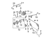
Toyota Solara Pulley
Part Number: 88412-06040$253.97 MSRP: $362.61You Save: $108.64 (30%)Ships in 1-3 Business DaysToyota Solara Clutch & Pulley
Part Number: 88410-06100$97.99 MSRP: $137.54You Save: $39.55 (29%)Ships in 1-3 Business Days
Toyota Solara Clutch
Part Number: 88410-06070$128.65 MSRP: $182.12You Save: $53.47 (30%)Ships in 1-3 Business Days
Toyota Solara Pulley
Part Number: 88412-42010$327.99 MSRP: $468.29You Save: $140.30 (30%)Ships in 1-3 Business Days

Toyota Solara A/C Clutch
Choose genuine A/C Clutch that pass strict quality control tests. You can trust the top quality and lasting durability. Shopping for OEM A/C Clutch for your Toyota Solara? Our website is your one-stop destination. We stock an extensive selection of genuine Toyota Solara parts. The price is affordable so you can save more. It only takes minutes to browse and find the exact fit. Easily add to cart and check out fast. Our hassle-free return policy will keep you stress-free. We process orders quickly for swift delivery. Your parts will arrive faster, so you can get back on the road sooner.
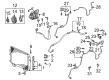
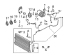
The A/C Clutch in Toyota Solara automobiles is one of those vital parts that is involved in the working of the air conditioning system of the vehicle; the elaborate operation of which is to convert the energy from the vehicle's engine and transmit that energy to the A/C clutch shaft. It operates when the A/C is turned on; this attracts a drum located in the belt pulley which locks the belt drive; the belt drive is free to rotate off. This mechanism eliminates undue load on other parts of the engine as well as other parts of the vehicle. These are the years when one or another problem may occur with the A/C Clutch - sticking, slipping, or even failure due to the impact of centrifugal force. Problems such as these may reduce the capacity and efficiency with which an A/C systems operate, cause an excessive use of fuel, and pose a risk to the actual compressor part and other accoutrements within an A/C system. When clutch failure occurs it is important to diagnose and repair all the other faults in the A/C system to ensure that they do not reoccur.
Toyota Solara A/C Clutch Parts and Q&A
- Q: How to service and repair the A/C Clutch on Toyota Solara?A:The compressor clutch servicing starts with running the engine at idle speed while activating A/C for 10 minutes followed by engine shutdown and negative (-) terminal battery cable separation. The first step involves both draining refrigerant gas from the refrigeration system along with the removal of the Drive Belt. To service 1MZ-FE engines it is necessary to eliminate the suction hose through bolt removal followed by wire harness clamp detachment and nut and bolt looseners. Fasten immediately placed caps onto open fittings to block moisture and dirt entry into the system. To disconnect the discharge hose users must remove its clamp bolt. The generator needs to be removed through three steps: first disconnect the generator connector then remove the nut and wire followed by disconnecting the wire harness from its clip and end with pivot bolt and plate washer and adjusting lock bolt removal. Engine models with 5S-FE require engineers to disconnect both suction and discharge hoses through removing the two bolts. The sequence for compressor removal includes disconnecting the connector then breaking loose and removing the 3 bolts. 1MZ-FE engine models need compressor removal that starts with disconnecting the connector then removing the 2 bolts, nut, drive belt adjusting bar bracket before completing with 3 bolts removal. To install the compressor on 5S-FE engine models users should first bolt it into position with three mounting points to 25 Nm (250 kg.cm, 18 ft.lb) torque and finally connect the connector. During installation of the compressor on 1MZ-FE models use the same torque value to install the three bolts followed by the installation of two bolts and a nut along with the drive belt adjusting bar bracket while satisfying torque specifications for Bolt (A) at 25 Nm (250 kg.cm, 18 ft.lb) and for Bolt (B) at 18 Nm (185 kg.cm, 13 ft.lb). Finally, join the connector. 5S-FE engine models require compressor oil lubrication for two new O-rings before installing them onto both hoses which need to be connected with 2 bolts at 10 Nm torque (100 kg.cm, 7 ft.lb). Attaching generators to their brackets requires placement of the pivot bolt followed by adjustment of the lock bolt while keeping it loose until detailed installation. Next, connect the generator wires and connectors. Screw the discharge hose by treating its new O-ring with ND-OIL 8 or equivalent oil then tighten the bolt to 10 Nm (100 kg.cm, 7 ft.lb). To install the suction hose users must first lubricate two new O-rings with compressor oil followed by hose installation then tight the bolt to 10 Nm (100 kg.cm, 7 ft.lb) with nut torque at 32 Nm (330 kg.cm, 24 ft.lb) before putting on the suction hose clamping bolt and wire harness clamp. The drive belt installation should be followed by negative (-) terminal cable reconnection while evacuating air then filling the refrigeration system with 800 plus or minus 50 g (28.22 plus or minus 1.76 oz.) of refrigerant. A gas leak detector must be used to check for refrigerant leaks followed by torque measurements at joints before A/C operation inspection begins.

Related Toyota Solara Parts
 Toyota Solara A/C Accumulator
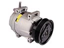 Toyota Solara A/C Compressor
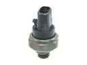 Toyota Solara A/C Compressor Cut-Out Switches
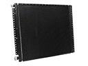 Toyota Solara A/C Condenser
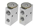 Toyota Solara A/C Expansion Valve
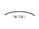 Toyota Solara A/C Hose
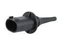 Toyota Solara Ambient Temperature Sensor
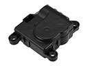 Toyota Solara Blend Door Actuator
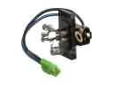 Toyota Solara Blower Motor Resistor
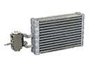 Toyota Solara Evaporator
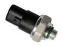 Toyota Solara HVAC Pressure Switch
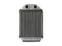 Toyota Solara Heater Core