×
ToyotaParts- Hello
- Login or Register
- Quick Links
- Live Chat
- Track Order
- Parts Availability
- RMA
- Help Center
- Contact Us
- Shop for
- Toyota Parts
- Scion Parts
My Garage
My Account
Cart
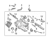
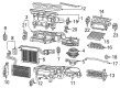
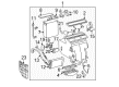
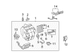
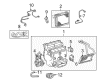
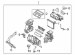
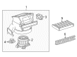
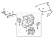
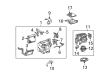
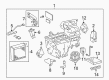
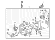
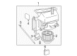
OEM Toyota Blower Motor Resistor
Heater Blower Motor Resistor- Select Vehicle by Model
- Select Vehicle by VIN
Select Vehicle by Model
orMake
Model
Year
Select Vehicle by VIN
For the most accurate results, select vehicle by your VIN (Vehicle Identification Number).
96 Blower Motor Resistors found


Toyota Resistor, Front Part Number: 87138-35050
$32.61 MSRP: $45.39You Save: $12.78 (29%)Ships in 1-3 Business DaysProduct Specifications- Other Name: Resistor, Blower; HVAC Blower Motor Resistor, Front; Resistor, Heater Blower; Blower Motor Resistor
- Position: Front


Toyota Resistor Part Number: 87138-04070
$37.63 MSRP: $52.38You Save: $14.75 (29%)Ships in 1-3 Business DaysProduct Specifications- Other Name: Resistor, Blower; HVAC Blower Motor Resistor; Blower Motor Resistor
- Replaces: 87138-04050


Toyota Blower Motor Resistor Part Number: 87138-26160
$32.01 MSRP: $44.56You Save: $12.55 (29%)Ships in 1-3 Business DaysProduct Specifications- Other Name: Resistor, Blower; HVAC Blower Motor Resistor; Blower Mtr Resistor; Resistor


Toyota Control Module, Rear Part Number: 87165-28020
$206.78 MSRP: $295.23You Save: $88.45 (30%)Ships in 1-3 Business DaysProduct Specifications- Other Name: Control, Blower Motor; HVAC Blower Motor Control Module, Rear; HVAC Control Module, Rear; Blower Motor Resistor; Controller; Resistor
- Position: Rear


Toyota Resistor Part Number: 87138-52030
$28.31 MSRP: $39.40You Save: $11.09 (29%)Ships in 1-2 Business DaysProduct Specifications- Other Name: Resistor, Blower; HVAC Blower Motor Resistor; Blower Motor Resistor


Toyota Resistor Part Number: 87138-52010
$27.47 MSRP: $38.24You Save: $10.77 (29%)Ships in 1-3 Business DaysProduct Specifications- Other Name: Resistor, Blower; HVAC Blower Motor Resistor; Blower Mtr Resistor; Blower Motor Resistor


Toyota Resistor, Rear Part Number: 87138-08050
$44.18 MSRP: $61.49You Save: $17.31 (29%)Ships in 1-3 Business DaysProduct Specifications- Other Name: Resistor, Blower; HVAC Blower Motor Resistor, Rear; Resistor, Blower (Rear); Blower Motor Resistor
- Position: Rear
- Replaces: 87138-08030


Toyota Transistor, Rear Part Number: 88750-52010
$139.65 MSRP: $197.68You Save: $58.03 (30%)Ships in 1-3 Business DaysProduct Specifications- Other Name: Transistor Assembly, Blower Resistor; HVAC Blower Motor Resistor, Rear; Resistor; Transistor Assembly, Blower Resistor(Rear); Blower Motor Resistor
- Position: Rear

Toyota Control Module, Rear Part Number: 87165-28010
$200.72 MSRP: $286.58You Save: $85.86 (30%)Ships in 1-3 Business DaysProduct Specifications- Other Name: Control, Blower Motor; HVAC Control Module, Rear; Blower Motor Resistor; Resistor
- Position: Rear


Toyota Fan Resistor Part Number: 87165-04010
$213.30 MSRP: $304.55You Save: $91.25 (30%)Ships in 1-3 Business DaysProduct Specifications- Other Name: Control, Blower Motor; Blower Motor Resistor; Resistor


Toyota Control, Blower Motor Part Number: 87165-32010
$220.64 MSRP: $315.02You Save: $94.38 (30%)Ships in 1-3 Business DaysProduct Specifications- Replaces: 87165-33010


Toyota Control Module Part Number: 87165-48010
$258.15 MSRP: $368.58You Save: $110.43 (30%)Ships in 1-3 Business DaysProduct Specifications- Other Name: Control, Blower Motor; HVAC Blower Motor Control Module; HVAC Control Module; Controller
- Manufacturer Note: LIMITED(USA)


Toyota Cover, Front Part Number: 88892-0C020
$24.25 MSRP: $33.75You Save: $9.50 (29%)Ships in 1-3 Business DaysProduct Specifications- Other Name: Cover, Cooler; Heater Core Access Cover, Front
- Position: Front


Toyota Resistor Part Number: 87138-WB001
$26.88 MSRP: $37.41You Save: $10.53 (29%)Ships in 1-3 Business DaysProduct Specifications- Other Name: Resistor, Blower; HVAC Blower Motor Resistor; Blower Motor Resistor


Toyota Resistor Part Number: 87138-0K090
$28.31 MSRP: $39.40You Save: $11.09 (29%)Ships in 1-3 Business DaysProduct Specifications- Other Name: Resistor, Blower; HVAC Blower Motor Resistor; Blower Motor Resistor

Toyota Blower Motor Resistor Part Number: 87138-02110
$29.39 MSRP: $40.90You Save: $11.51 (29%)Product Specifications- Other Name: Resistor, Blower; HVAC Blower Motor Resistor; Resistor
- Manufacturer Note: AIR CONDITIONER-MANUAL


Toyota Blower Motor Resistor Part Number: 87138-60280
$32.01 MSRP: $44.56You Save: $12.55 (29%)Ships in 1-2 Business DaysProduct Specifications- Other Name: Resistor, Blower; HVAC Blower Motor Resistor; Resistor


Toyota Resistor Part Number: 87138-02080
$31.56 MSRP: $43.94You Save: $12.38 (29%)Ships in 1-2 Business DaysProduct Specifications- Other Name: Resistor, Blower; HVAC Blower Motor Resistor; Blower Mtr Resistor; Blower Motor Resistor
- Replaces: 87138-02030


Toyota Blower Motor Resistor Part Number: 87138-48040
$35.60 MSRP: $49.55You Save: $13.95 (29%)Ships in 1-3 Business DaysProduct Specifications- Other Name: Resistor, Blower; Resistor


Toyota Resistor Part Number: 87138-33060
$35.60 MSRP: $49.55You Save: $13.95 (29%)Ships in 1 Business DayProduct Specifications- Other Name: Resistor, Blower; HVAC Blower Motor Resistor; Blower Motor Resistor
- Manufacturer Note: W(MANUAL AIR CONDITIONER)
- Replaces: 87138-33030
| Page 1 of 5 |Next >
1-20 of 96 Results
Toyota Blower Motor Resistor
OEM parts deliver unmatched quality you can rely on. They pass extensive quality control inspections. Toyota produces them to the official factory specifications. This process helps prevent defects and imperfections. So you can get exceptional lifespan and a flawless fit. Need new OEM Toyota Blower Motor Resistor? You'll love our wide selection of genuine options. Shop in minutes and skip the hunt. Our prices are unbeatable, you'll save time and money. It's easy to shop and find the right piece. Our committed customer service team gives professional help from start to finish. Every part includes a manufacturer's warranty. We ship quickly, your parts will arrive fast at your door.
Blower Motor Resistor maintains an unchanging cabin fan speed that ensures year-long control of airflow in the car. Toyota was founded in 1937 in Japan and gained world confidence through waste reduction, employee empowerment, and stamping out defects before the automobiles come out of the production line, a philosophy that has allowed assembly plants to remain versatile and low-cost in production while still withstanding challenging production reliability standards. Toyota keeps advancing the TNGA platform, reducing center of gravity and enhancing handling without adding a lot of weight, and crash protection is hardened without adding a lot of weight. Small city cars and massive SUVs have parts that are easy to work with, and parts reduce wastage even more. Toyota expanded hybrid options in small hatches all the way up to plug-in crossovers; that efficiency can get behind durability mile after mile, and the new drive systems can now permit families to drive on electric power alone and only turn to gasoline when it's time to go out of town. The Blower Motor Resistor is between the cabin switch and the fan that reduces voltage across fixed resistive coils such that each speed setting receives the exact amount of current necessary, which translates to you feeling corresponding amounts of air being flowed to you as soon as you turn the dial. The Blower Motor Resistor is an instant reacting one. Blower Motor Resistor in any modern Toyota is also applied to protect the circuit against surges that may melt plugs and burn the wires whenever one takes a long trip over the summer road. When it finally breaks, replacement of the Blower Motor Resistor will restore silent air circulation and will save the blower motor from overheating.
Toyota Blower Motor Resistor Parts and Q&A
- Q: How to install the blower motor resistor on Toyota FJ Cruiser?A:Begin installation of the blower motor resistor by attaching it using 2 screws after connector connection. Proceed to connect the cable to the negative battery terminal but ensure you apply a torque force of 3.9 Nm (40 kgf-cm, 35 in-lbf).
- Q: How to install the Blower Motor Resistor and the associated components on Toyota Highlander?A:The blower motor controller needs secure attachment with its two screws followed by connector connection. Afterward install the roof side inner garnish assembly RH, deck trim side panel assembly RH, front deck side trim cover RH, No. 1 luggage compartment trim hook, rope hook assembly (for RH side), rear combination light service cover RH, side trim cover RH (for Manual Air Conditioning System), and rear room temperature sensor (for Automatic Air Conditioning System). Begin by fixing the rear seat side garnish cap and deck side trim cover RH and deck side trim RH as well as the rear floor finish plate and rear No. 2 seat assembly and connect the rear seat lap type belt assembly LH and RH. The installation process includes adding rear No. 2 seat inner belt assembly, rear mat, deck floor board assembly, deck side trim box LH, rear seat side cover LH, deck side trim box RH, jack carrier assembly, jack assembly, jack carrier cushion, jack carrier support, rear seat side cover RH, tonneau cover assembly (w/ Tonneau Cover), No. 2 deck board sub-assembly, No. 3 deck board sub-assembly, deck board assembly, rear door opening trim Weather Strip RH, and rear door scuff plate RH.


Related Toyota Parts
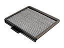 Toyota Cabin Air Filter
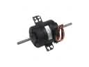 Toyota Blower Motor
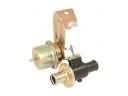 Toyota Heater Control Valve
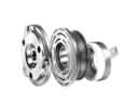 Toyota A/C Compressor Clutch
 Toyota Ambient Temperature Sensor
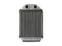 Toyota Heater Core
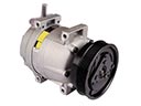 Toyota A/C Compressor
 Toyota A/C Hose
 Toyota A/C Service Cap
 Toyota A/C System Valve Core
 Toyota Blower Control Switches
 Toyota HVAC Pressure Switch