×
ToyotaParts- Hello
- Login or Register
- Quick Links
- Live Chat
- Track Order
- Parts Availability
- RMA
- Help Center
- Contact Us
- Shop for
- Toyota Parts
- Scion Parts
My Garage
My Account
Cart
OEM Scion tC Timing Chain
Engine Timing Chain- Select Vehicle by Model
- Select Vehicle by VIN
Select Vehicle by Model
orMake
Model
Year
Select Vehicle by VIN
For the most accurate results, select vehicle by your VIN (Vehicle Identification Number).
4 Timing Chains found


Scion tC Timing Chain Part Number: 13507-28010
$92.18 MSRP: $129.39You Save: $37.21 (29%)Ships in 1-2 Business Days

Scion tC Timing Chain Part Number: 13506-0V010
$210.74 MSRP: $300.88You Save: $90.14 (30%)Ships in 1-2 Business Days

Scion tC Timing Chain Part Number: 13506-0H011
$268.87 MSRP: $383.89You Save: $115.02 (30%)Ships in 1-2 Business Days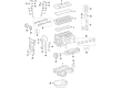
Scion tC Timing Chain Part Number: 13506-36030
$209.11 MSRP: $298.55You Save: $89.44 (30%)Ships in 1-3 Business Days
Scion tC Timing Chain
Choose genuine Timing Chain that pass strict quality control tests. You can trust the top quality and lasting durability. Shopping for OEM Timing Chain for your Scion tC? Our website is your one-stop destination. We stock an extensive selection of genuine Scion tC parts. The price is affordable so you can save more. It only takes minutes to browse and find the exact fit. Easily add to cart and check out fast. Our hassle-free return policy will keep you stress-free. We process orders quickly for swift delivery. Your parts will arrive faster, so you can get back on the road sooner.
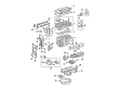
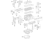
Timing Chain is one of the most essential parts that define the durability and the functioning of Scion tC models. This metal chain connects the camshaft and crankshaft so that the valves in the engine open and close at specifically orchestrated times. The Timing Chain is not like the rubber timing belt that needs to be replaced often while the timing chain is very durable and does not require as much maintenance and gives drivers a sense of security. Due to its compatibility across different tC models, this modification appeals to both figurant and ordinary users who want to bring the premier out of their cars. It is evident that with the timing chain at the center of the Scion tC, specifically its I4 2AR-FE engine, it can be considered that the car's design gains a significant boost. It prevents the events of failure resulting from wear and tear, inadequate lubrication of the Timing Chain enhances a smooth engine operation. However, the Timing Chain is different and remains popular in the market because it has little wear and no need for replacement as it is traditionally done for timing belts. Also, besides the customized interior and exterior of the Scion tC, they are affordable and especially targeted at the youthful market. Since the timing chain is an important part, the Timing Chain has the potential to significantly affect the overall driving experience, thus keeping the tC in high demand among the consumers.
Scion tC Timing Chain Parts and Q&A
- Q: How to install the No. 2 Timing Chain sub-assembly on Scion tC?A:Set the crankshaft key in its left horizontal position before aligning the yellow mark links with the timing marks of each gear while turning the cutout of the drive shaft to the top. Position the gears from crankshaft and oil pump shaft together with the chain encircling them and use the nut to set/install the oil pump drive shaft gear before you will tighten it briefly. Add the damper spring to the adjusting hole followed by the chain tensioner plate installation along with a bolt and torque the bolt to 12 Nm (122 kgf-cm, 9 ft-lbf). Set the adjusting hole of the oil pump drive shaft gear to match the oil pump groove before inserting a 4 mm diameter bar to stabilize the gear. Afterward, tighten the nut to 29.5 Nm (301 kgf-cm, 22 ft-lbf). When the crankshaft reaches a 90 degrees clockwise position the key on the crankshaft will move upward. Start by putting the crankshaft timing sprocket together with the No. 1 chain vibration damper and securing them with two bolts that should be tightened to 9.0 Nm (92 kgf-cm, 80 in-lbf). The operator must first align the compression marks on the No. 1 cylinder by rotating the camshafts with wrenches and next apply the timing chain to the crankshaft timing sprocket while maintaining the gold or orange mark link at the timing mark position on the crankshaft timing gear. The service tool 09309-37010 along with a hammer helps to tap in the crankshaft sprocket. The sprocket installation requires precise alignment of the gold/yellow links with each camshaft gear timing mark. The chain tensioner slipper gets bolted with 19 Nm (194 kgf-cm, 14 ft-lbf) torque while the timing chain guide utilizes a 9.0 Nm (92 kgf-cm, 80 in-lbf) torque. Apply seal packing (Diameter 2.0 mm (0.079 in.)) on the timing chain cover sub-assembly before installing it with care to do so within 3 minutes and avoid adding engine oil for at least 2 hours after installation. Install the cover by tightening 14 bolts and 2 nuts at specific torque values to 9.0 Nm (92 kgf-cm, 80 in-lbf for bolt A), 25 Nm (255 kgf-cm, 18 ft-lbf for bolt B), and 55 Nm (561 kgf-cm, 41 ft-lbf for bolt C), while tightening the nut to 11 Nm (112 kgf-cm, 8 ft-lbf). Insert the stud bolt for the V-ribbed belt tensioner with an E10 "TORX" socket then torques it to 21.5 Nm (219 kgf-cm, 16 ft-lbf). Before installing the chain tensioner elements, users must release the ratchet pawl, push in the plunger, and hook it to the pin before adding a new gasket followed by tightening the two nuts to 9.0 Nm (92 kgf-cm, 80 in-lbf). Fix the pulley using Special Service Tool: 09213-54015 91651-60855 to maintain stability during bolt tightening before torque is applied to 180 Nm (1,835 kgf-cm, 133 ft-lbf). Turn the crankshaft counterclockwise first to free the plunger knock pin from the hook then turn it clockwise to verify the plunger extension. Attach the wire harness protector clamp and tighten its bolt to 8.4 Nm with torque value set at 85 kgf-cm and 74 in-lbf. Installation of the oil pan sub-assembly requires users to remove outdated packing materials followed by the application of a continuous bead of seal packing (Diameter 3.0 to 4.0 mm (0.118 to 0.157 in.)) before mounting the oil pan to the cylinder block using uniform 12 bolt and 2 nut torque of 9.0 Nm (92 kgf-cm, 80 in-lbf). A transmission jack inserted beneath the engine should rest on a wooden block before the chain block and sling device are stripped away along with the No. 1 and No. 2 engine hangers. It is necessary to install two components in the following order: crankshaft position sensor followed by V-ribbed belt tensioner assembly installed with a bolt plus nut torqued to 59.5 Nm (607 kgf-cm, 44 ft-lbf). The cylinder head cover sub-assembly needs installation through removal of old packing material for seal packing application at specified locations. Clamp the cover using eight bolts and two nuts which require installing torque measures of 11 Nm (112 kgf-cm, 8 ft-lbf for bolt A), 14 Nm (143 kgf-cm, 10 ft-lbf for bolt B), and 11 Nm (112 kgf-cm, 8 ft-lbf for nut). Screw a bolt marked A to 8.4 Nm (86 kgf-cm, 74 in-lbf) and secure B clamps along with the installation of 2 ventilation hoses to the cylinder head cover. The engine mounting insulator on the right-hand side requires installation with 4 bolts then 2 nuts tightened to 52 Nm (530 kgf-cm, 38 ft-lbf). Simultaneously install the front engine mounting insulator using a bolt and a nut which needs torquing to 52 Nm (530 kgf-cm, 38 ft-lbf). Then connect the 2 clamps of the engine wire. The wire harness protector gets installed with a bolt followed by the No. 1 oil reservoir bracket that receives 2 bolts with 7.8 Nm (80 kgf-cm, 69 in-lbf) torque while the vane pump oil reservoir mounts to the bracket and the radiator reservoir gets bolted with 5.0 Nm (51 kgf-cm, 44 in-lbf) torque. The installation of the No. 1 engine cover sub-assembly requires 2 nuts to be tightened to 7.0 Nm torque (71 kgf-cm, 62 in-lbf) before continuing with the front fender apron seal RH followed by engine under cover LH and engine under cover RH on front wheel RH and hood sub-assembly repair. System initialization must be performed after negative (-) battery terminal cable removal and reconnection.
- Q: How to remove the timing chain on Scion tC?A:Disconnection of the negative cable from the battery and waiting ninety seconds is essential when removing a 2AZ-FE timing chain to avoid Air Bag activation. Begin by removing the hood sub-assembly with the front wheel RH as well as engine under covers RH and LH along with the front fender apron seal RH and No. 1 engine cover sub-assembly through the removal of their corresponding 2 nuts. The first step requires draining engine coolant followed by removal of the front Exhaust Pipe assembly with fan & generator V belt and generator assembly and vane pump assembly. The engine mounting insulator RH requires removal by unbolted radiator reservoir and the vane pump oil reservoir needs separation from the No. 1 oil reservoir bracket without breaking connected 2 oil reservoir hoses followed by removal of all necessary bolts and nuts. The engine wire clamps should be disconnected while lowering the engine with a transmission jack. The procedure requires the Ignition Coil assembly and cylinder head cover sub-assembly removal after disconnecting ventilation hoses and engine wire and V-ribbed belt tensioner assembly removal during engine elevation. Install the engine hangers at positions 1 and 2 before securing the engine with a chain block during a bolt and nut removal operation of the Crankshaft Position Sensor combined with the oil pan sub-assembly. The work technician performs precise cutting of the applied sealer when removing the oil pan. To set the No. 1 cylinder at TDC/compression you must align the crankshaft pulley groove with "0" mark and both camshaft timing gears need proper alignment. Begin by fixing the crankshaft pulley using Special Service Tools: 09213-54015 91651-60855 to loosen the bolt before removing it with the Special Tools: 09950-50013 09951-05010. It is necessary to remove the No. 1 chain tensioner assembly together with the timing chain cover sub-assembly while safeguarding contact surfaces. Then extract the No. 1 crankshaft position sensor plate and timing chain guide along with the chain tensioner slipper. Finally, obtain the chain sub-assembly, No. 1 chain vibration damper, crankshaft timing sprocket, and No. 2 chain sub-assembly after aligning the oil pump drive shaft gear by turning the crankshaft and securing it in position followed by component removal.


Related Scion tC Parts
 Scion tC Oil Filter
 Scion tC Engine Cover
 Scion tC Cylinder Head
 Scion tC Cam Gear
 Scion tC Camshaft Bearing
 Scion tC Engine Mount
 Scion tC Intake Valve
 Scion tC Oil Drain Plug Gasket
 Scion tC Oil Pump Spring
 Scion tC Rod Bearing
 Scion tC Valve Stem Seal
 Scion tC Variable Timing Sprocket
Browse Scion tC Timing Chain by Years
2016 2015 2014 2013 2012 2011 2010 2009 2008 2007 2006 2005