×
ToyotaParts- Hello
- Login or Register
- Quick Links
- Live Chat
- Track Order
- Parts Availability
- RMA
- Help Center
- Contact Us
- Shop for
- Toyota Parts
- Scion Parts
My Garage
My Account
Cart
OEM 2008 Scion tC Timing Chain
Engine Timing Chain- Select Vehicle by Model
- Select Vehicle by VIN
Select Vehicle by Model
orMake
Model
Year
Select Vehicle by VIN
For the most accurate results, select vehicle by your VIN (Vehicle Identification Number).
2 Timing Chains found


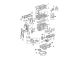
2008 Scion tC Timing Chain
Part Number: 13506-0H011$268.87 MSRP: $383.89You Save: $115.02 (30%)Ships in 1-2 Business DaysProduct Specifications- Other Name: Chain Sub-Assembly, Timing; Engine Timing Chain; Chain Sub-Assembly
- Replaces: 13506-28020, 13506-0H031, 13506-28010, 13506-28011, 13506-28021, 13506-0H010
- Part Name Code: 13506
- Item Weight: 1.20 Pounds
- Item Dimensions: 6.8 x 3.4 x 1.4 inches
- Condition: New
- Fitment Type: Direct Replacement
- SKU: 13506-0H011
- Warranty: This genuine part is guaranteed by Toyota's factory warranty.


2008 Scion tC Timing Chain
Part Number: 13507-28010$89.46 MSRP: $125.57You Save: $36.11 (29%)Ships in 1-2 Business DaysProduct Specifications- Other Name: Chain Sub-Assembly, Oil; Engine Timing Chain; Chain; Chain Sub-Assembly
- Replaces: 13507-0H020
- Part Name Code: 13507
- Item Weight: 0.70 Pounds
- Item Dimensions: 2.6 x 2.4 x 0.4 inches
- Condition: New
- Fitment Type: Direct Replacement
- SKU: 13507-28010
- Warranty: This genuine part is guaranteed by Toyota's factory warranty.
2008 Scion tC Timing Chain
Looking for affordable OEM 2008 Scion tC Timing Chain? Explore our comprehensive catalogue of genuine 2008 Scion tC Timing Chain. All our parts are covered by the manufacturer's warranty. Plus, our straightforward return policy and speedy delivery service ensure an unparalleled shopping experience. We look forward to your visit!
2008 Scion tC Timing Chain Parts Q&A
- Q: How to install the timing chain on 2008 Scion tC?A: Installing the timing chain requires first putting the crankshaft key in the left horizontal position while rotating the cutout of the drive shaft to reach the top. Start installation of the timing chain when you position the yellow mark links relative to the gears' timing marks on each component. Next, put the gears onto the crankshaft and oil pump shaft with the chain in place before securely tightening the oil pump drive shaft gear with its nut. The adjustable chain tensioner plate must receive a bolt installation followed by torquing it to 12 Nm (122 kgf-cm, 9 ft-lbf). Position the adjusting hole of the oil pump drive shaft gear against the oil pump groove before fixing it in place with a 4 mm diameter bar while tightening the nut to 29.5 Nm (301 kgf-cm, 22 ft-lbf). Position the crankshaft key facing upward by turning it clockwise 90 degrees before installing the crankshaft timing sprocket with its vibration damper and 2 bolts secured at 9.0 Nm torque. Furnish the No. 1 cylinder to TDC/compression alignment while positioning the camshaft timing gear's timing marks against bearing caps. Then place the chain onto the crankshaft timing sprocket where the gold or orange mark link faces the timing mark. The special tool 09309-37010 will help to tap the crankshaft timing sprocket while ensuring alignment of gold/yellow links against the camshaft timing gear and sprocket timing marks before you install the chain. Screw in the chain tensioner slipper while tightening the bolt to 19 Nm (194 kgf-cm, 14 ft-lbf) and the timing chain guide needs a bolt torque of 9.0 Nm (92 kgf-cm, 80 in-lbf). Position the No. 1 crankshaft position sensor plate with its "F" orientation forward before removing the old packing from the timing chain cover surfaces for the application of seal packing material with a 2.0 mm (0.079 in.) diameter. Ensure the packing contact surfaces remain free of oil residue. Install the timing chain cover with its 14 bolts along with 2 nuts according to the specified torque values starting at 9.0 Nm (92 kgf-cm, 80 in-lbf) through 25 Nm (255 kgf-cm, 18 ft-lbf) up to 55 Nm (561 kgf-cm, 41 ft-lbf) and ending at 11 Nm (112 kgf-cm, 8 ft-lbf). You should use an E10 "torx" socket to install the stud bolt of the V-ribbed belt tensioner while applying 21.5 Nm (219 kgf-cm, 16 ft-lbf) torque. Secure the chain tensioner assembly No. 1 by first pushing the plunger completely in and hooking it before adding a new gasket and torquing the two nuts to 9.0 Nm (92 kgf-cm, 80 in-lbf). Fasten the crankshaft pulley by using Special Service Tool: 09213-54015 91651-60855 while tightening the bolt to 180 Nm (1,835 kgf-cm, 133 ft-lbf). The plunger extension must be checked after knocking off the plunger knock pin then bolting the wire harness protector clamp before torquing the bolt at 8.4 Nm (85 kgf-cm, 74 in-lbf). The oil pan installation requires removal of old packing material from contact surfaces followed by application of continuous seal packing bead (3.0-4.0 mm diameter material) before tightening bolted 12 cylinder block mountings and 2 nuts to 9.0 Nm (92 kgf-cm, 80 in-lbf). Perform the installation by supporting the engine with a transmission jack before disconnecting both chain block and hangers. The replacement process requires installation of the crankshaft position sensor and V-ribbed belt tensioner assembly as well as the cylinder head cover using 8 bolts and 2 nuts while maintaining specified torque settings. The torques needed are: 11 Nm (112 kgf-cm, 8 ft-lbf) and 14 Nm (143 kgf-cm, 10 ft-lbf). The next step includes installing the engine wire and attaching ventilation hoses prior to mounting the engine insulator RH with 4 bolts and 2 nuts tightened to 52 Nm (530 kgf-cm, 38 ft-lbf). Torque the front engine mounting insulator to 7.8 Nm (80 kgf-cm, 69 in-lbf) while installing the engine wire clamps and the wire harness protector together with the No.1 oil reservoir bracket. The installation process includes adding the return tube followed by installing the radiator reservoir combined with the vane pump assembly. Next, the generator assembly and the front exhaust pipe assembly should be installed together with the fan and generator V belt. The procedure for engine oil addition includes connecting the cable to the negative terminal followed by leak inspections then securing the No. 1 engine cover assembly with 2 nuts at 7.0 Nm (71 kgf-cm, 62 in-lbf). Perform the initialization steps on system components that need it following the battery terminal reconnection then proceed with installing the front fender apron seal RH followed by engine under covers LH and RH and the front wheel and hood sub-assembly.
Related 2008 Scion tC Parts
 2008 Scion tC Oil Filter
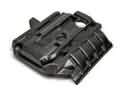 2008 Scion tC Engine Cover
 2008 Scion tC Dipstick
 2008 Scion tC Oil Pan
 2008 Scion tC Crankshaft Thrust Washer Set
 2008 Scion tC Engine Mount
 2008 Scion tC Harmonic Balancer
 2008 Scion tC Oil Pump
 2008 Scion tC Piston Ring Set
 2008 Scion tC Timing Chain Guide
 2008 Scion tC Timing Cover
 2008 Scion tC Variable Timing Sprocket