×
ToyotaParts- Hello
- Login or Register
- Quick Links
- Live Chat
- Track Order
- Parts Availability
- RMA
- Help Center
- Contact Us
- Shop for
- Toyota Parts
- Scion Parts
My Garage
My Account
Cart
OEM 2009 Toyota Tacoma Knock Sensor
Engine Knock Sensor- Select Vehicle by Model
- Select Vehicle by VIN
Select Vehicle by Model
orMake
Model
Year
Select Vehicle by VIN
For the most accurate results, select vehicle by your VIN (Vehicle Identification Number).
1 Knock Sensor found


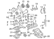
2009 Toyota Tacoma Knock Sensor
Part Number: 89615-06010$138.05 MSRP: $195.42You Save: $57.37 (30%)Ships in 1-3 Business DaysProduct Specifications- Other Name: Sensor, Knock Control; Ignition Knock (Detonation) Sensor
- Replaces: 89615-BZ030, 89615-20090, 89615-BZ040
- Part Name Code: 89615
- Item Weight: 0.40 Pounds
- Item Dimensions: 4.1 x 1.9 x 1.4 inches
- Condition: New
- Fitment Type: Direct Replacement
- SKU: 89615-06010
- Warranty: This genuine part is guaranteed by Toyota's factory warranty.
2009 Toyota Tacoma Knock Sensor
Looking for affordable OEM 2009 Toyota Tacoma Knock Sensor? Explore our comprehensive catalogue of genuine 2009 Toyota Tacoma Knock Sensor. All our parts are covered by the manufacturer's warranty. Plus, our straightforward return policy and speedy delivery service ensure an unparalleled shopping experience. We look forward to your visit!
2009 Toyota Tacoma Knock Sensor Parts Q&A
- Q: How to remove the Knock Sensor on 2009 Toyota Tacoma?A: You must disconnect the negative battery terminal cable as the first step when removing the Knock Sensor. After disconnecting the negative terminal cable you should proceed to remove the engine under cover sub-assembly that exists on 4WD and Pre-Runner vehicles. First drain engine coolant before removing the intake air connector. Secondly step is to take off the throttle with motor body assembly. Erase all connections from the fuel hose and fuel hose No.2. Unscrew the fuel vapor feed hose at the VSV along with the vacuum hose and clamp bracket bolt before the intake manifold can be taken off. The maintenance technician should first disconnect water by-pass hose No. 2 followed by ventilation hose No. 3 and VSV connector. The engine wire harness clamp and compressor magnetic clutch connector need to be separated when using air conditioning. Follow the illustration by removing the nut together with the bolt and harness clamp bracket then detach the three connectors. Apply sequence to disconnect the relay block first then release the intake manifold by removing five bolts along with two nuts. The knock control sensor removal process requires disconnecting its connector followed by removing the bolt until the sensor can be extracted.
Related 2009 Toyota Tacoma Parts
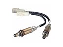 2009 Toyota Tacoma Oxygen Sensor
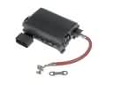 2009 Toyota Tacoma Fuse Box
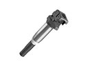 2009 Toyota Tacoma Ignition Coil
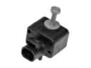 2009 Toyota Tacoma Air Bag Sensor
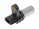 2009 Toyota Tacoma Camshaft Position Sensor
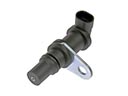 2009 Toyota Tacoma Crankshaft Position Sensor
 2009 Toyota Tacoma Engine Control Module
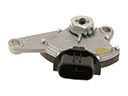 2009 Toyota Tacoma Neutral Safety Switch
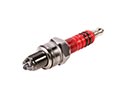 2009 Toyota Tacoma Spark Plug
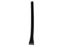 2009 Toyota Tacoma Antenna Mast
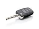 2009 Toyota Tacoma Car Key
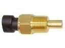 2009 Toyota Tacoma Coolant Temperature Sensor