×
ToyotaParts- Hello
- Login or Register
- Quick Links
- Live Chat
- Track Order
- Parts Availability
- RMA
- Help Center
- Contact Us
- Shop for
- Toyota Parts
- Scion Parts
My Garage
My Account
Cart
OEM 2009 Toyota Highlander Axle Shaft
Car Axle Shaft- Select Vehicle by Model
- Select Vehicle by VIN
Select Vehicle by Model
orMake
Model
Year
Select Vehicle by VIN
For the most accurate results, select vehicle by your VIN (Vehicle Identification Number).
11 Axle Shafts found


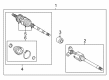
2009 Toyota Highlander Shaft Assembly, Front Drive
Part Number: 43420-0W280$558.34 MSRP: $844.78You Save: $286.44 (34%)Ships in 1-3 Business DaysProduct Specifications- Other Name: SHAFT ASSY, FR DRIVE; CV Axle Assembly; Axle Shaft
- Position: Front Driver Side
- Replaces: 43420-0W230
- Item Weight: 14.40 Pounds
- Item Dimensions: 31.6 x 7.6 x 6.7 inches
- Condition: New
- SKU: 43420-0W280
- Warranty: This genuine part is guaranteed by Toyota's factory warranty.

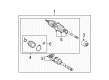
2009 Toyota Highlander Axle Assembly, Passenger Side
Part Number: 43410-0W200$428.79 MSRP: $628.40You Save: $199.61 (32%)Ships in 1-3 Business DaysProduct Specifications- Other Name: Shaft Assembly, Front Drive; CV Axle Assembly, Front Right; GSP Cv Axle; Axle Shaft; Shaft Assembly, Front Drive, Passenger Side; CV Axle Assembly
- Position: Passenger Side
- Part Name Code: 43410
- Item Weight: 14.60 Pounds
- Item Dimensions: 30.1 x 7.5 x 6.6 inches
- Condition: New
- Fitment Type: Direct Replacement
- SKU: 43410-0W200
- Warranty: This genuine part is guaranteed by Toyota's factory warranty.


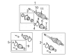
2009 Toyota Highlander Axle Assembly, Driver Side
Part Number: 43420-0W220$308.77 MSRP: $467.38You Save: $158.61 (34%)Product Specifications- Other Name: Shaft Assembly, Front Drive; CV Axle Assembly, Front Left; GSP Cv Axle; Axle Shaft; Shaft Assembly, Front Drive, Driver Side; CV Axle Assembly
- Position: Driver Side
- Part Name Code: 43420
- Item Weight: 14.50 Pounds
- Item Dimensions: 29.5 x 7.5 x 6.7 inches
- Condition: New
- Fitment Type: Direct Replacement
- SKU: 43420-0W220
- Warranty: This genuine part is guaranteed by Toyota's factory warranty.

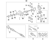
2009 Toyota Highlander Axle Assembly, Rear
Part Number: 42340-48081$369.43 MSRP: $541.41You Save: $171.98 (32%)Ships in 1-3 Business DaysProduct Specifications- Other Name: Shaft Assembly, Rear Drive; CV Axle Assembly, Rear, Rear Left, Rear Right; GSP Cv Axle; Axle Shaft; Shaft Assembly, Rear Drive, Passenger Side; Shaft Assembly, Rear Drive, Driver Side; CV Axle Assembly
- Position: Rear
- Replaces: 42340-48080
- Condition: New
- Fitment Type: Direct Replacement
- SKU: 42340-48081
- Warranty: This genuine part is guaranteed by Toyota's factory warranty.
2009 Toyota Highlander Axle Assembly, Front Passenger Side
Part Number: 43410-0W240$697.65 MSRP: $1048.95You Save: $351.30 (34%)Product Specifications- Other Name: Shaft Assembly, Front Drive; CV Axle Assembly, Front Right; CV Axle Assembly; GSP Cv Axle; Axle Shaft
- Position: Front Passenger Side
- Item Weight: 15.90 Pounds
- Item Dimensions: 44.1 x 6.5 x 5.3 inches
- Condition: New
- SKU: 43410-0W240
- Warranty: This genuine part is guaranteed by Toyota's factory warranty.

2009 Toyota Highlander Outer CV Joint, Rear
Part Number: 42370-49245$245.80 MSRP: $350.95You Save: $105.15 (30%)Ships in 1-3 Business DaysProduct Specifications- Other Name: Shaft Assembly, Rear Drive; CV Joint; Outer Joint; Rear Drive Outboard Joint, Passenger & Driver Side Shaft Assembly
- Position: Rear
- Item Weight: 14.10 Pounds
- Item Dimensions: 33.3 x 6.3 x 5.8 inches
- Condition: New
- Fitment Type: Direct Replacement
- SKU: 42370-49245
- Warranty: This genuine part is guaranteed by Toyota's factory warranty.
2009 Toyota Highlander Axle Assembly, Passenger Side
Part Number: 43410-48110$456.37 MSRP: $668.82You Save: $212.45 (32%)Ships in 1-3 Business DaysProduct Specifications- Other Name: Shaft Assembly, Front Drive; CV Axle Assembly, Front Right; GSP Cv Axle; Axle Shaft; Shaft Assembly, Front Drive, Passenger Side; CV Axle Assembly
- Position: Passenger Side
- Part Name Code: 43410
- Item Weight: 14.00 Pounds
- Item Dimensions: 31.0 x 7.6 x 6.8 inches
- Condition: New
- Fitment Type: Direct Replacement
- SKU: 43410-48110
- Warranty: This genuine part is guaranteed by Toyota's factory warranty.
2009 Toyota Highlander Axle Assembly, Passenger Side
Part Number: 43410-0W210$410.40 MSRP: $601.45You Save: $191.05 (32%)Ships in 1-3 Business DaysProduct Specifications- Other Name: Shaft Assembly, Front Drive; CV Axle Assembly, Front Right; GSP Cv Axle; Axle Shaft; Shaft Assembly, Front Drive, Passenger Side; CV Axle Assembly
- Position: Passenger Side
- Part Name Code: 43410
- Item Weight: 15.30 Pounds
- Item Dimensions: 29.5 x 7.3 x 6.6 inches
- Condition: New
- Fitment Type: Direct Replacement
- SKU: 43410-0W210
- Warranty: This genuine part is guaranteed by Toyota's factory warranty.
2009 Toyota Highlander Axle Assembly, Driver Side
Part Number: 43420-48140$382.03 MSRP: $559.87You Save: $177.84 (32%)Ships in 1-3 Business DaysProduct Specifications- Other Name: Shaft Assembly, Front Drive; CV Axle Assembly, Front Left; Axle Shaft; Shaft Assembly, Front Drive, Driver Side
- Position: Driver Side
- Part Name Code: 43420
- Item Weight: 14.10 Pounds
- Item Dimensions: 30.7 x 7.4 x 6.9 inches
- Condition: New
- Fitment Type: Direct Replacement
- SKU: 43420-48140
- Warranty: This genuine part is guaranteed by Toyota's factory warranty.

2009 Toyota Highlander Axle Shaft Assembly, Rear
Part Number: 42340-48070$380.89 MSRP: $558.21You Save: $177.32 (32%)Ships in 1-3 Business DaysProduct Specifications- Other Name: Shaft Assembly, Rear Drive; CV Axle Assembly, Rear, Rear Left, Rear Right; GSP Cv Axle; Axle Shaft; Axle Assembly; Shaft Assembly, Rear Drive, Passenger Side; Shaft Assembly, Rear Drive, Driver Side; CV Axle Assembly
- Manufacturer Note: TYPE B:REFER ILLUST.
- Position: Rear
- Item Weight: 15.50 Pounds
- Item Dimensions: 28.4 x 8.5 x 7.5 inches
- Condition: New
- Fitment Type: Direct Replacement
- SKU: 42340-48070
- Warranty: This genuine part is guaranteed by Toyota's factory warranty.
2009 Toyota Highlander Axle Assembly, Driver Side
Part Number: 43420-0W240$378.06 MSRP: $554.05You Save: $175.99 (32%)Product Specifications- Other Name: Shaft Assembly, Front Drive; CV Axle Assembly, Front Left; GSP Cv Axle; Axle Shaft; Shaft Assembly, Front Drive, Driver Side; CV Axle Assembly
- Position: Driver Side
- Part Name Code: 43420
- Item Weight: 14.40 Pounds
- Item Dimensions: 29.5 x 7.4 x 6.4 inches
- Condition: New
- Fitment Type: Direct Replacement
- SKU: 43420-0W240
- Warranty: This genuine part is guaranteed by Toyota's factory warranty.
2009 Toyota Highlander Axle Shaft
Looking for affordable OEM 2009 Toyota Highlander Axle Shaft? Explore our comprehensive catalogue of genuine 2009 Toyota Highlander Axle Shaft. All our parts are covered by the manufacturer's warranty. Plus, our straightforward return policy and speedy delivery service ensure an unparalleled shopping experience. We look forward to your visit!
2009 Toyota Highlander Axle Shaft Parts Q&A
- Q: How to remove and replace the axle shaft assembly on 2009 Toyota Highlander?A: The first step to remove and replace the front drive shaft assembly for the 1AR-FE engine requires removing the three undercovers starting with No. 1 engine, then No. 2 engine, then the floor under cover from the left-hand side. Drain automatic transaxle fluid while removing the front wheels from the vehicle. The left side front axle hub nut release requires Special Service Tool: 09930-00010 and requires hammer use to unstake the part while applying brakes before removing the nut. Infiniti technicians should split the front stabilizer link assembly while also separating the front speed sensor, tie rod assembly, No. 1 front suspension lower arm and front axle assembly from the left wheel side. Use Special Service Tools 09520-01010, 09520-24010, and 09520-32040 to remove the left front drive shaft assembly with caution toward the dust cover, boot, oil seal, and dropped assembly. The right-hand side installation requires the technician to remove the bearing bracket hole snap ring from the drive shaft bearing bracket and disconnect the bolt and front drive shaft assembly. Secure the left front axle hub sub-assembly by using Special Service Tool: 09608-16042, 09608-02021, and 09608-02041 but be aware the hub bearing risks damage when supporting weight equivalent to the vehicle.
Related 2009 Toyota Highlander Parts
 2009 Toyota Highlander Control Arm
 2009 Toyota Highlander CV Boot
 2009 Toyota Highlander CV Joint
 2009 Toyota Highlander Coil Springs
 2009 Toyota Highlander Differential Mount
 2009 Toyota Highlander Lateral Link
 2009 Toyota Highlander Rear Crossmember
 2009 Toyota Highlander Suspension Strut Rod
 2009 Toyota Highlander Sway Bar Bracket
 2009 Toyota Highlander Sway Bar Bushing
 2009 Toyota Highlander Sway Bar Kit
 2009 Toyota Highlander Wheel Seal