×
ToyotaParts- Hello
- Login or Register
- Quick Links
- Live Chat
- Track Order
- Parts Availability
- RMA
- Help Center
- Contact Us
- Shop for
- Toyota Parts
- Scion Parts
My Garage
My Account
Cart
OEM 2009 Toyota FJ Cruiser Knock Sensor
Engine Knock Sensor- Select Vehicle by Model
- Select Vehicle by VIN
Select Vehicle by Model
orMake
Model
Year
Select Vehicle by VIN
For the most accurate results, select vehicle by your VIN (Vehicle Identification Number).
1 Knock Sensor found


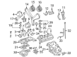
2009 Toyota FJ Cruiser Knock Sensor
Part Number: 89615-06010$138.05 MSRP: $195.42You Save: $57.37 (30%)Ships in 1-3 Business DaysProduct Specifications- Other Name: Sensor, Knock Control; Ignition Knock (Detonation) Sensor
- Replaces: 89615-BZ030, 89615-20090, 89615-BZ040
- Part Name Code: 89615
- Item Weight: 0.40 Pounds
- Item Dimensions: 4.1 x 1.9 x 1.4 inches
- Condition: New
- Fitment Type: Direct Replacement
- SKU: 89615-06010
- Warranty: This genuine part is guaranteed by Toyota's factory warranty.
2009 Toyota FJ Cruiser Knock Sensor
Looking for affordable OEM 2009 Toyota FJ Cruiser Knock Sensor? Explore our comprehensive catalogue of genuine 2009 Toyota FJ Cruiser Knock Sensor. All our parts are covered by the manufacturer's warranty. Plus, our straightforward return policy and speedy delivery service ensure an unparalleled shopping experience. We look forward to your visit!
2009 Toyota FJ Cruiser Knock Sensor Parts Q&A
- Q: How to install the knock sensors and complete the assembly process on 2009 Toyota FJ Cruiser?A: Start by installing the 2 knock sensors through 2 bolts secured with 20 Nm (204 kgf-cm, 15 ft-lbf) torque while connecting the 2 knock sensor connectors. The installation process requires you to attach the No. 1 water outlet pipe using 3 bolts at 10 Nm (102 kgf-cm, 7.4 ft-lbf) torque and to connect 4 wire harness clamps. The heater water inlet hose must be joined to the water outlet pipe. Start with checking the cylinder head set bolt before installing the cylinder head gasket followed by the cylinder head sub-assembly. After installing the No. 2 camshaft bearing you should mount the Bank 1 camshafts before moving on to the No. 2 chain tensioner assembly. After the Bank 1 camshaft timing gears and the No. 2 chain install the mechanic should proceed to mount the water by-pass joint RR next along with the intake manifold. Take necessary steps to connect both the No. 2 fuel pipe sub-assembly and the No. 1 fuel pipe sub-assembly. The service procedure begins by installing exhaust manifold sub-assembly RH and manifold stay before adding the front exhaust pipe assembly and completing with the No. 2 front exhaust pipe assembly. Exhaust pipe stopper brackets along with the No.1 cool air inlet should be installed on 4WD models. The chain sub-assembly needs to be installed before checking fuel leaks and exhaust gas leaks while inspecting ignition timing alongside engine idling speed checks and compression and CO/HC examinations and front wheel alignment assessment.
Related 2009 Toyota FJ Cruiser Parts
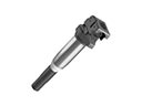 2009 Toyota FJ Cruiser Ignition Coil
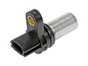 2009 Toyota FJ Cruiser Camshaft Position Sensor
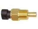 2009 Toyota FJ Cruiser Coolant Temperature Sensor
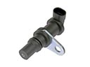 2009 Toyota FJ Cruiser Crankshaft Position Sensor
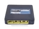 2009 Toyota FJ Cruiser Engine Control Module
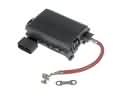 2009 Toyota FJ Cruiser Fuse Box
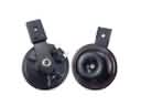 2009 Toyota FJ Cruiser Horn
 2009 Toyota FJ Cruiser Neutral Safety Switch
 2009 Toyota FJ Cruiser Oxygen Sensor
 2009 Toyota FJ Cruiser Relay
 2009 Toyota FJ Cruiser Spark Plug
 2009 Toyota FJ Cruiser Transmitter