×
ToyotaParts- Hello
- Login or Register
- Quick Links
- Live Chat
- Track Order
- Parts Availability
- RMA
- Help Center
- Contact Us
- Shop for
- Toyota Parts
- Scion Parts
My Garage
My Account
Cart
OEM 2008 Toyota Highlander Control Arm
Suspension Arm- Select Vehicle by Model
- Select Vehicle by VIN
Select Vehicle by Model
orMake
Model
Year
Select Vehicle by VIN
For the most accurate results, select vehicle by your VIN (Vehicle Identification Number).
2 Control Arms found


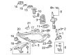
2008 Toyota Highlander Arm Sub-Assembly, Front Suspension, Lower Driver Side
Part Number: 48069-0E050$159.79 MSRP: $226.20You Save: $66.41 (30%)Ships in 1-2 Business DaysProduct Specifications- Other Name: Arm Sub-Assembly, Suspension; Control Arm
- Position: Lower Driver Side
- Replaces: 48069-0T011, 48069-48070, 48069-48041, 48069-0T010, 48069-48040
- Part Name Code: 48069
- Item Weight: 8.50 Pounds
- Item Dimensions: 7.1 x 1.6 x 1.4 inches
- Condition: New
- Fitment Type: Direct Replacement
- SKU: 48069-0E050
- Warranty: This genuine part is guaranteed by Toyota's factory warranty.


2008 Toyota Highlander Control Arm, Passenger Side
Part Number: 48068-0E050$159.79 MSRP: $226.20You Save: $66.41 (30%)Ships in 1-2 Business DaysProduct Specifications- Other Name: Arm Sub-Assembly, Suspension; Suspension Control Arm, Front Right; Control Arm Assembly; Lower Control Arm; Arm Sub-Assembly, Front Suspension, Lower Passenger Side
- Position: Passenger Side
- Replaces: 48068-48040, 48068-0T010, 48068-0T011, 48068-48041, 48068-48070
- Part Name Code: 48068
- Item Weight: 9.10 Pounds
- Item Dimensions: 7.1 x 1.4 x 1.5 inches
- Condition: New
- Fitment Type: Direct Replacement
- SKU: 48068-0E050
- Warranty: This genuine part is guaranteed by Toyota's factory warranty.
2008 Toyota Highlander Control Arm
Looking for affordable OEM 2008 Toyota Highlander Control Arm? Explore our comprehensive catalogue of genuine 2008 Toyota Highlander Control Arm. All our parts are covered by the manufacturer's warranty. Plus, our straightforward return policy and speedy delivery service ensure an unparalleled shopping experience. We look forward to your visit!
2008 Toyota Highlander Control Arm Parts Q&A
- Q: How to control the removal of the rear Control Arm on 2008 Toyota Highlander?A: The rear lower arm removal procedure for 2WD begins with deck board assembly removal followed by removal of both the No. 3 deck board sub-assembly with tonneau cover and the No. 2 deck board sub-assembly with tonneau cover until you reach the tonneau cover assembly before proceeding to the rear mat then the service hole cover and lastly the spare wheel carrier and its components. The procedure begins by discarding the rear mat and continuing with removal of the deck trim service hole cover together with the lower spare wheel carrier hinge cover. Once the spare tire is removed it is necessary to extract the spare wheel carrier lock cover along with its corresponding cover before taking off the rear wheel. To separate the rear stabilizer link assembly LH users must remove the nut but when the ball joint turns with this nut they need to use a hexagon wrench (5 mm) to hold the stud bolt. Carry out the identical procedures for the rear stabilizer link assembly that exists on the right-hand side. First separate the rear stabilizer bar and after that remove the rear No. 2 suspension arm assembly by unfastening its bolt and uninstalling the nut to disconnect it from the rear axle carrier sub-assembly while ensuring proper bolt loosening due to the stopper nut. To finish the task remove the rear No. 1 suspension arm assembly while loosening the bolt because of the stopper nut before separating it from the rear axle carrier sub-assembly through bolt and nut removal.
Related 2008 Toyota Highlander Parts
 2008 Toyota Highlander Ball Joint
 2008 Toyota Highlander Bump Stop
 2008 Toyota Highlander Coil Springs
 2008 Toyota Highlander Crossmember Bushing
 2008 Toyota Highlander Lateral Link
 2008 Toyota Highlander Shock And Strut Mount
 2008 Toyota Highlander Steering Knuckle
 2008 Toyota Highlander Sway Bar Bracket
 2008 Toyota Highlander Sway Bar Bushing
 2008 Toyota Highlander Sway Bar Kit
 2008 Toyota Highlander Sway Bar Link
 2008 Toyota Highlander Wheel Seal