×
ToyotaParts- Hello
- Login or Register
- Quick Links
- Live Chat
- Track Order
- Parts Availability
- RMA
- Help Center
- Contact Us
- Shop for
- Toyota Parts
- Scion Parts
My Garage
My Account
Cart
OEM 2008 Scion xB Sway Bar Kit
Stabilizer Sway Bar Set- Select Vehicle by Model
- Select Vehicle by VIN
Select Vehicle by Model
orMake
Model
Year
Select Vehicle by VIN
For the most accurate results, select vehicle by your VIN (Vehicle Identification Number).
1 Sway Bar Kit found

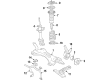
2008 Scion xB Stabilizer Bar, Front
Part Number: 48811-12A50$104.51 MSRP: $146.69You Save: $42.18 (29%)Ships in 1-3 Business DaysProduct Specifications- Other Name: Bar, Stabilizer; Suspension Stabilizer Bar, Front; Sway Bar; Bar, Stabilizer, Front
- Position: Front
- Part Name Code: 48811
- Item Weight: 8.10 Pounds
- Item Dimensions: 44.2 x 11.9 x 4.9 inches
- Condition: New
- Fitment Type: Direct Replacement
- SKU: 48811-12A50
- Warranty: This genuine part is guaranteed by Toyota's factory warranty.
2008 Scion xB Sway Bar Kit
Looking for affordable OEM 2008 Scion xB Sway Bar Kit? Explore our comprehensive catalogue of genuine 2008 Scion xB Sway Bar Kit. All our parts are covered by the manufacturer's warranty. Plus, our straightforward return policy and speedy delivery service ensure an unparalleled shopping experience. We look forward to your visit!
2008 Scion xB Sway Bar Kit Parts Q&A
- Q: How to install the front Sway Bar Kit and related components on 2008 Scion xB?A: Installation of the front sway bar kit starts with adding the No. 1 front sway bar bush for the LH side to the front sway bar kit. Install the bushings with their dust lips facing out while the cutouts face towards the rear. The installation process should also be done for the RH side. The front sway bar kit should be placed onto the front suspension crossmember sub-assembly with the identification mark positioned on the right side. Use four bolts to install the front suspension member front brace LH while torquing them to 87 Nm (887 kgf-cm, 64 ft-lbf), temporarily tightening bolt A then fully tighten in the order of B, C, D, A while ensuring the No. 1 front sway bar bushing protrudes from its position. Use the same procedure for attaching the front suspension member front brace right-hand side. First place the front lower No. 1 suspension arm sub-assembly LH onto its temporary position before adding the front suspension crossmember sub-assembly then install the front suspension member brace rear LH and rear RH by following this approach. After implementing both front suspension member reinforcements the technician should attach the front suspension sub-assemblies which include both the LH and RH lower No. 1 suspension arms. Install both tie rod end sub-assembly parts after connecting them before attaching the front sway bar link assemblies to both LH and RH sides. Succeeding steps entail the assembly of the No. 1 steering column hole cover sub-assembly and the No. 2 steering intermediate shaft assembly combined with the column hole cover silencer sheet. The engine under covers must be installed during maintenance in this sequence: start with rear RH followed by rear LH and then move to No. 2 before installing final cover at No. 1. Complete the installation by adding front wheels followed by suspension stabilization then fully tighten the front lower No. 1 suspension arm sub-assembly LH and perform front wheel alignment checks and adjustments.
Related 2008 Scion xB Parts
 2008 Scion xB Wheel Bearing
 2008 Scion xB Ball Joint
 2008 Scion xB Bump Stop
 2008 Scion xB Coil Spring Insulator
 2008 Scion xB Coil Springs
 2008 Scion xB Control Arm
 2008 Scion xB Control Arm Bolt
 2008 Scion xB Shock And Strut Mount
 2008 Scion xB Shock and Strut Boot
 2008 Scion xB Steering Knuckle
 2008 Scion xB Strut Housing
 2008 Scion xB Sway Bar Bushing