×
ToyotaParts- Hello
- Login or Register
- Quick Links
- Live Chat
- Track Order
- Parts Availability
- RMA
- Help Center
- Contact Us
- Shop for
- Toyota Parts
- Scion Parts
My Garage
My Account
Cart
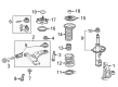
OEM 2008 Scion xB Control Arm
Suspension Arm- Select Vehicle by Model
- Select Vehicle by VIN
Select Vehicle by Model
orMake
Model
Year
Select Vehicle by VIN
For the most accurate results, select vehicle by your VIN (Vehicle Identification Number).
2 Control Arms found


2008 Scion xB Arm Sub-Assembly, Front Suspension, Lower Driver Side
Part Number: 48069-12300$168.48 MSRP: $238.50You Save: $70.02 (30%)Ships in 1-3 Business DaysProduct Specifications- Other Name: Arm Sub-Assembly, Suspension; Suspension Control Arm; Control Arm
- Position: Lower Driver Side
- Part Name Code: 48069
- Item Weight: 3.70 Pounds
- Item Dimensions: 22.8 x 3.6 x 16.6 inches
- Condition: New
- Fitment Type: Direct Replacement
- SKU: 48069-12300
- Warranty: This genuine part is guaranteed by Toyota's factory warranty.


2008 Scion xB Lower Control Arm, Passenger Side
Part Number: 48068-12300$159.08 MSRP: $225.20You Save: $66.12 (30%)Ships in 1-3 Business DaysProduct Specifications- Other Name: Arm Sub-Assembly, Suspension; Suspension Control Arm, Front Right; Control Arm Assembly; Arm Sub-Assembly, Front Suspension, Lower Passenger Side; Control Arm
- Position: Passenger Side
- Part Name Code: 48068
- Item Weight: 10.80 Pounds
- Item Dimensions: 23.0 x 3.6 x 17.8 inches
- Condition: New
- Fitment Type: Direct Replacement
- SKU: 48068-12300
- Warranty: This genuine part is guaranteed by Toyota's factory warranty.
2008 Scion xB Control Arm
Looking for affordable OEM 2008 Scion xB Control Arm? Explore our comprehensive catalogue of genuine 2008 Scion xB Control Arm. All our parts are covered by the manufacturer's warranty. Plus, our straightforward return policy and speedy delivery service ensure an unparalleled shopping experience. We look forward to your visit!
2008 Scion xB Control Arm Parts Q&A
- Q: How to install the front lower Control Arms on 2008 Scion xB?A: Position the front suspension crossmember on a level surface then use 2 bolts and a nut with each side to couple the front lower No. 1 suspension arm sub-assembly RH and LH temporarily. Tighten only the bolt while keeping the nut fixed. Use the transmission jack to stabilize the front suspension crossmember while applying Special Service Tool: 09670-00020 for alternate tightening of the following components: Bolts A at 145 Nm (1479 kgf-cm, 107 ft-lbf), Bolts B at 95 Nm (969 kgf-cm, 70 ft-lbf), Nuts at 95 Nm (969 kgf-cm, 70 ft-lbf). Secure the front suspension member brace rear LH using one bolt with 145 Nm torque and the other bolt requiring 93 Nm torque. The front suspension member reinforcement requires 4 mounting bolts per side requiring a torque sequence of C followed by B then D and finishing with A at 96 Nm (979 kgf-cm and 71 ft-lbf). Fix the nut of the front lower No. 1 suspension arm sub-assembly LH for manual transaxle before tightening the bolt. Connect the sub-assemblies of front lower No. 1 suspension arm LH and RH followed by tie rod end assemblies LH and RH. Insert the front stabilizer link assemblies LH and RH using a hexagon wrench for installation but torque them to 74 Nm (755 kgf-cm, 55 ft.lbf). First connect the No. 1 steering column hole cover sub-assembly and the No. 2 steering intermediate shaft assembly following installation of the column hole cover silencer sheet and engine under covers. Follow the installation of front wheels with 103 Nm (1050 kgf-cm, 76 ft-lbf) torque and lower the vehicle then stabilize the suspension through multiple press-downs. Secure the front lower No. 1 suspension arm sub-assembly using Special Service Tool: 09961-01270 by tightening bolt A (172 Nm (1755 kgf-cm, 127 ft-lbf) with the tool or 233 Nm (2376 kgf-cm, 172 ft-lbf) without it). Then fully tighten bolt B to 233 Nm (2376 kgf-cm, 172 ft-lbf). The inspection of front wheel alignment should be both conducted along with its adjustments.
Related 2008 Scion xB Parts
 2008 Scion xB Sway Bar Link
 2008 Scion xB Wheel Hub
 2008 Scion xB Ball Joint
 2008 Scion xB Bump Stop
 2008 Scion xB Coil Spring Insulator
 2008 Scion xB Shock Absorber
 2008 Scion xB Shock And Strut Mount
 2008 Scion xB Shock and Strut Boot
 2008 Scion xB Steering Knuckle
 2008 Scion xB Strut Housing
 2008 Scion xB Sway Bar Bushing
 2008 Scion xB Sway Bar Kit