×
ToyotaParts- Hello
- Login or Register
- Quick Links
- Live Chat
- Track Order
- Parts Availability
- RMA
- Help Center
- Contact Us
- Shop for
- Toyota Parts
- Scion Parts
My Garage
My Account
Cart
OEM 2006 Toyota Sequoia Sway Bar Kit
Stabilizer Sway Bar Set- Select Vehicle by Model
- Select Vehicle by VIN
Select Vehicle by Model
orMake
Model
Year
Select Vehicle by VIN
For the most accurate results, select vehicle by your VIN (Vehicle Identification Number).
4 Sway Bar Kits found

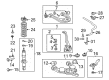
2006 Toyota Sequoia Stabilizer Bar, Front
Part Number: 48811-AF030$159.67 MSRP: $226.04You Save: $66.37 (30%)Ships in 1-3 Business DaysProduct Specifications- Other Name: Bar, Stabilizer; Suspension Stabilizer Bar, Front; Sway Bar; Bar, Stabilizer, Front
- Manufacturer Note: W(REAR STABILIZER)
- Position: Front
- Part Name Code: 48811
- Item Weight: 7.50 Pounds
- Item Dimensions: 43.8 x 12.0 x 4.9 inches
- Condition: New
- Fitment Type: Direct Replacement
- SKU: 48811-AF030
- Warranty: This genuine part is guaranteed by Toyota's factory warranty.
2006 Toyota Sequoia Stabilizer Bar, Front
Part Number: 48811-AF040$154.03 MSRP: $218.05You Save: $64.02 (30%)Ships in 1-3 Business DaysProduct Specifications- Other Name: Bar, Stabilizer; Suspension Stabilizer Bar, Front; Sway Bar; Bar, Stabilizer, Front
- Manufacturer Note: W(AIR SUSPENSION)
- Position: Front
- Part Name Code: 48811
- Item Weight: 7.50 Pounds
- Item Dimensions: 43.4 x 12.0 x 4.9 inches
- Condition: New
- Fitment Type: Direct Replacement
- SKU: 48811-AF040
- Warranty: This genuine part is guaranteed by Toyota's factory warranty.

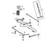
2006 Toyota Sequoia Stabilizer Bar, Rear
Part Number: 48812-AF020$135.82 MSRP: $192.27You Save: $56.45 (30%)Ships in 1-3 Business DaysProduct Specifications- Other Name: Bar, Stabilizer, Rear; Suspension Stabilizer Bar, Rear; Sway Bar
- Position: Rear
- Part Name Code: 48812
- Item Weight: 5.20 Pounds
- Item Dimensions: 41.6 x 9.1 x 3.4 inches
- Condition: New
- Fitment Type: Direct Replacement
- SKU: 48812-AF020
- Warranty: This genuine part is guaranteed by Toyota's factory warranty.
2006 Toyota Sequoia Stabilizer Bar, Rear
Part Number: 48812-AF010$119.02 MSRP: $168.49You Save: $49.47 (30%)Ships in 1-3 Business DaysProduct Specifications- Other Name: Bar, Stabilizer, Rear; Suspension Stabilizer Bar, Rear; Sway Bar
- Manufacturer Note: W(SUN ROOF)
- Position: Rear
- Part Name Code: 48812
- Item Weight: 5.10 Pounds
- Item Dimensions: 42.0 x 9.1 x 3.4 inches
- Condition: New
- Fitment Type: Direct Replacement
- SKU: 48812-AF010
- Warranty: This genuine part is guaranteed by Toyota's factory warranty.
2006 Toyota Sequoia Sway Bar Kit
Looking for affordable OEM 2006 Toyota Sequoia Sway Bar Kit? Explore our comprehensive catalogue of genuine 2006 Toyota Sequoia Sway Bar Kit. All our parts are covered by the manufacturer's warranty. Plus, our straightforward return policy and speedy delivery service ensure an unparalleled shopping experience. We look forward to your visit!
2006 Toyota Sequoia Sway Bar Kit Parts Q&A
- Q: How to service and repair the front Sway Bar Kit on 2006 Toyota Sequoia?A: Service and repair operations on the front sway bar kit begin with removing front sway bar link assemblies through sway bar link separation from lower suspension arms while stabilization with a 6 mm hexagon wrench is needed when ball joint rotation occurs with the nut. Starting with the front sway bar kit requires removing two bolts and nuts which leads to the removal of the sway bar kit with corresponding cushions and brackets before detaching its brackets and cushions. It is important to first grip the front sway bar link while unscrewing its nut before removing the link and 2 retainers and bushings from each side. You must inspect the ball joint by stroking the steering knuckle and upper suspension arm. Then, install the protector along with the ball joint. Use 4 bolts with a set nuts to hang it temporarily while tightening the nuts to 159 Nm (1,621 kgf-cm, 117 ft. lbs.). Adjust the nut to 60 degrees if the cotter pin holes don't align correctly. Use a new cotter pin to join the tie rod end to the lower ball joint while torquing it to 91 Nm (930 kgf-cm, 67 ft. lbs.) and then recheck the installation if needed. The steering alignment needs inspection and the sensors require zero point calibration after tightening the front lower ball joint bolts to 65 Nm (663 kgf-cm, 48 ft. lbs.). The front wheel should be measured at 110 Nm (1,150 kgf-cm, 83 ft. lbs.). Check the ball joint boot of the front sway bar link for damage by operating the ball joint stud five times until the nut reaches a torque range of 0.05 to 2.0 Nm (0.5 to 20 kgf-cm, 0.4 to 17 inch lbs.). The sway bar kit will be installed through front sway bar link attachment which involves bushing and retainer installation onto the sway bar kit followed by new nut tightening to 19 Nm (190 kgf-cm, 14 ft. lbs.) and then repeating the process on both sides. The front sway bar kit installation requires 2 bushings facing back while using 2 brackets to secure it with nuts and bolts which must be torqued to 37 Nm (377 kgf-cm, 27 ft. lbs.). Front sway bar links need installation to the suspension lower arm with 69 Nm (700 kgf-cm, 51 ft. lbs.) tightening while a hexagon (6 mm) wrench stabilizes the nut when the ball joint rotates.
Related 2006 Toyota Sequoia Parts
 2006 Toyota Sequoia Control Arm
 2006 Toyota Sequoia Alignment Bolt
 2006 Toyota Sequoia Ball Joint
 2006 Toyota Sequoia Bump Stop
 2006 Toyota Sequoia Front Cross-Member
 2006 Toyota Sequoia Lateral Link
 2006 Toyota Sequoia Shock Absorber
 2006 Toyota Sequoia Shock And Strut Mount
 2006 Toyota Sequoia Steering Knuckle
 2006 Toyota Sequoia Strut Housing
 2006 Toyota Sequoia Sway Bar Bracket
 2006 Toyota Sequoia Sway Bar Bushing