×
ToyotaParts- Hello
- Login or Register
- Quick Links
- Live Chat
- Track Order
- Parts Availability
- RMA
- Help Center
- Contact Us
- Shop for
- Toyota Parts
- Scion Parts
My Garage
My Account
Cart
OEM 2002 Toyota Highlander Wheel Hub
Wheel Axle Hub- Select Vehicle by Model
- Select Vehicle by VIN
Select Vehicle by Model
orMake
Model
Year
Select Vehicle by VIN
For the most accurate results, select vehicle by your VIN (Vehicle Identification Number).
4 Wheel Hubs found


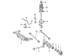
2002 Toyota Highlander Hub Assembly, Front
Part Number: 43502-0E030$130.65 MSRP: $184.95You Save: $54.30 (30%)Product Specifications- Other Name: Hub Sub-Assembly, Front Axle; Wheel Hub, Front; Front Hub & Bearing; Front Hub; Hub
- Position: Front
- Replaces: 43502-AA021, 43502-28100, 43502-08010, 43502-AA020
- Item Weight: 5.10 Pounds
- Item Dimensions: 6.6 x 6.9 x 4.6 inches
- Condition: New
- SKU: 43502-0E030
- Warranty: This genuine part is guaranteed by Toyota's factory warranty.


2002 Toyota Highlander Hub & Bearing Assembly, Rear Axle, Driver Side
Part Number: 42460-48011$478.62 MSRP: $701.43You Save: $222.81 (32%)Ships in 1-2 Business DaysProduct Specifications- Other Name: Hub&Bearing Assembly, Rear Axle; Wheel Hub Repair Kit; Bearing; Axle Bearing
- Position: Driver Side
- Replaces: 42460-06021, 42460-06020, 42460-48010, 42460-06030
- Part Name Code: 42450B
- Item Weight: 8.50 Pounds
- Item Dimensions: 7.0 x 6.8 x 7.3 inches
- Condition: New
- Fitment Type: Direct Replacement
- SKU: 42460-48011
- Warranty: This genuine part is guaranteed by Toyota's factory warranty.


2002 Toyota Highlander Hub Assembly, Front
Part Number: 43502-28090$129.36 MSRP: $183.12You Save: $53.76 (30%)Ships in 1-3 Business DaysProduct Specifications- Other Name: Hub Sub-Assembly, Front Axle; Wheel Hub, Front; Front Hub; Hub; Hub Sub-Assembly, Front Axle, Passenger Side; Hub Sub-Assembly, Front Axle, Driver Side; Wheel Hub
- Manufacturer Note: (J)
- Position: Front
- Replaces: 43502-AA010, 43502-AA011
- Item Weight: 4.10 Pounds
- Item Dimensions: 6.7 x 6.7 x 4.5 inches
- Condition: New
- Fitment Type: Direct Replacement
- SKU: 43502-28090
- Warranty: This genuine part is guaranteed by Toyota's factory warranty.
2002 Toyota Highlander Hub Assembly, Passenger Side
Part Number: 42450-48011$515.62 MSRP: $755.65You Save: $240.03 (32%)Ships in 1 Business DayProduct Specifications- Other Name: Hub&Bearing Assembly, Rear Axle; Rear Right Wheel Bearing & Hub; Wheel Hub Repair Kit; Axle Bearing; Hub & Bearing Assembly, Rear Axle, Passenger Side; Wheel Bearing and Hub Assembly
- Position: Passenger Side
- Replaces: 42450-06030, 42450-48010, 42450-06020, 42450-06021, 42450-48020
- Part Name Code: 42450A
- Item Weight: 9.10 Pounds
- Item Dimensions: 6.8 x 6.9 x 7.7 inches
- Condition: New
- Fitment Type: Direct Replacement
- SKU: 42450-48011
- Warranty: This genuine part is guaranteed by Toyota's factory warranty.
2002 Toyota Highlander Wheel Hub
Looking for affordable OEM 2002 Toyota Highlander Wheel Hub? Explore our comprehensive catalogue of genuine 2002 Toyota Highlander Wheel Hub. All our parts are covered by the manufacturer's warranty. Plus, our straightforward return policy and speedy delivery service ensure an unparalleled shopping experience. We look forward to your visit!
2002 Toyota Highlander Wheel Hub Parts Q&A
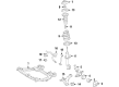
- Q: How to replace the Front Wheel Hub LH on 2002 Toyota Highlander?A: Prefixing Service Tool 09930-00010 along with a hammer will help you unstake the lock nut of Front Wheel Hub LH after which you can remove the lock nut by applying steady pressure on the brake pedal. Customers must remove the bolt from the speed sensor front LH then disconnect the sensor wire and flexible hose connected to the shock absorber followed by taking the speed sensor apart from the steering knuckle. Take out the two bolts from the front disc brake caliper assembly LH and proceed to eliminate the front disc. To separate the tie rod assembly LH users must first remove its nut and cotter pin before using Special Service Tool: 09628-62011 to disconnect the tie rod end from the steering knuckle. Dismantle the front suspension arm sub-assembly lower No. 1 LH by extracting its bolt and two nuts, and break free the front wheel assembly LH through a plastic hammer stroke to disconnect the drive shaft from the wheel hub without damaging the boot or ABS speed sensor rotor. To remove the lower ball joint assembly front LH, users should first remove the cotter pin and nut followed by using Special Service Tool: 09628-62011 to detach the ball joint. The front wheel bearing dust deflector No. 1 LH requires a screwdriver to remove it while using a snap ring plier to remove the front wheel hub LH hole snap ring. The front wheel hub sub-assembly LH can be removed with Special Service Tool: 09520-00031 while Special Service Tools: 09950-00020, 09950-60010 (09951-00410), 09950-70010 (09951-07100) and a press will be needed to extract the inner race from the wheel hub. Remove the front wheel hub bearing by applying the bearing's inner race onto the hub followed by Special Service Tool: 09527-17011 then 09950-60010 (09951-00600) and 09950-70010 (09951-07100) which can be used to press until the bearing touches the tool. First position the steering knuckle horizontally and use Special Service Tool: 09950-60010 (09951-00600), 09950-70010 (09951-07100) along with a press to eliminate the bearing. To install the front wheel hub LH bearing you must use Special Service Tool: 09950-60020 (09951-00680), 09950-70010 (09951-07100) together with a press. Then install the dust cover followed by applying torques to the 4 bolts using a torx wrench (T30). The procedure involves using Special Service Tool: 09608-32010, 09950-60020 (09951-00680), 09950-70010 (09951-07100) and a press to install the front wheel hub sub-assembly LH followed by installing a new snap ring with a snap ring plier. Install the front wheel bearing dust deflector No. 1 LH with the help of Special Service Tool: 09316-60011 (09316-00011, 09316-00031), 09608-32010 and a hammer by ensuring the ABS speed sensor holes stay properly aligned. Fasten the lower ball joint assembly front LH while tightening the nut to 123 Nm (1,250 kgf-cm, 90 ft. lbs.) and add a new cotter pin by properly adjusting the nut when needed. Freely install the front wheel assembly LH by attaching its 2 bolts and nuts to the shock absorber at 210 Nm torque (2,143 kgf-cm, 155 ft. lbs.) while ensuring that the drive shaft assembly splines properly engage. Connect both lower suspension arm sub-assembly lower No. 1 LH components with a bolt and 2 nuts before torquing them to 127 Nm (1,300 kgf-cm, 94 ft.lbs.). Continuing with the procedure, secure the tie rod assembly LH to the steering knuckle through a new nut and cotter pin application using 49 Nm (500 kgf-cm, 36 ft.lbs.). You should reinstall the front disc followed by the front disc brake caliper assembly LH into the steering knuckle using two bolts secured with a torque of 106.9 Nm (1,090 kgf-cm, 79 ft. lbs.). Drive the installer to install the front wheel hub LH nut and the front wheel while torquing to 103 Nm (1,050 kgf-cm, 76 ft. lbs.). Then the front wheel alignment needs inspection and adjustment and a check of the ABS speed sensor signal.
Related 2002 Toyota Highlander Parts
 2002 Toyota Highlander Wheel Bearing
 2002 Toyota Highlander Backing Plate
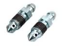 2002 Toyota Highlander Brake Bleeder Screw
 2002 Toyota Highlander Brake Caliper Bracket
 2002 Toyota Highlander Brake Disc
 2002 Toyota Highlander Brake Line
 2002 Toyota Highlander Brake Pad Set
 2002 Toyota Highlander Parking Brake Shoe
 2002 Toyota Highlander Spindle Nut
 2002 Toyota Highlander Wheel Cylinder
 2002 Toyota Highlander Wheel Stud
 2002 Toyota Highlander Yaw Sensor