×
ToyotaParts- Hello
- Login or Register
- Quick Links
- Live Chat
- Track Order
- Parts Availability
- RMA
- Help Center
- Contact Us
- Shop for
- Toyota Parts
- Scion Parts
My Garage
My Account
Cart
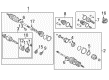
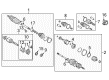
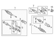
OEM 2001 Toyota Celica Axle Shaft
Car Axle Shaft- Select Vehicle by Model
- Select Vehicle by VIN
Select Vehicle by Model
orMake
Model
Year
Select Vehicle by VIN
For the most accurate results, select vehicle by your VIN (Vehicle Identification Number).
12 Axle Shafts found

2001 Toyota Celica Axle Assembly, Passenger Side
Part Number: 43410-20800$468.03 MSRP: $685.90You Save: $217.87 (32%)Ships in 1-3 Business DaysProduct Specifications- Other Name: Shaft Assembly, Front Drive; CV Axle Assembly, Front Right; GSP Cv Axle; Axle Shaft; Shaft Assembly, Front Drive, Passenger Side; CV Axle Assembly
- Manufacturer Note: W(ABS)
- Position: Passenger Side
- Part Name Code: 43410
- Item Weight: 27.50 Pounds
- Item Dimensions: 43.3 x 5.5 x 5.5 inches
- Condition: New
- Fitment Type: Direct Replacement
- SKU: 43410-20800
- Warranty: This genuine part is guaranteed by Toyota's factory warranty.

2001 Toyota Celica Axle Assembly, Passenger Side
Part Number: 43410-20760$450.95 MSRP: $660.87You Save: $209.92 (32%)Ships in 1-3 Business DaysProduct Specifications- Other Name: Shaft Assembly, Front Drive; CV Axle Assembly, Front Right; Axle Shaft; Shaft Assembly, Front Drive, Passenger Side
- Position: Passenger Side
- Part Name Code: 43410
- Item Weight: 25.30 Pounds
- Item Dimensions: 43.7 x 5.6 x 5.5 inches
- Condition: New
- Fitment Type: Direct Replacement
- SKU: 43410-20760
- Warranty: This genuine part is guaranteed by Toyota's factory warranty.

2001 Toyota Celica Axle Assembly, Passenger Side
Part Number: 43410-20771$450.60 MSRP: $660.35You Save: $209.75 (32%)Ships in 1-3 Business DaysProduct Specifications- Other Name: Shaft Assembly, Front Drive; CV Axle Assembly, Front Right; GSP Cv Axle; Axle Shaft; Shaft Assembly, Front Drive, Passenger Side; CV Axle Assembly
- Position: Passenger Side
- Replaces: 43410-20770
- Part Name Code: 43410
- Item Weight: 19.20 Pounds
- Item Dimensions: 43.7 x 5.5 x 5.4 inches
- Condition: New
- Fitment Type: Direct Replacement
- SKU: 43410-20771
- Warranty: This genuine part is guaranteed by Toyota's factory warranty.
2001 Toyota Celica Axle Assembly, Passenger Side
Part Number: 43410-20781$449.71 MSRP: $659.06You Save: $209.35 (32%)Ships in 1-3 Business DaysProduct Specifications- Other Name: Shaft Assembly, Front Drive; CV Axle Assembly, Front Right; GSP Cv Axle; Axle Shaft; Shaft Assembly, Front Drive, Passenger Side; CV Axle Assembly
- Manufacturer Note: W(ABS)
- Position: Passenger Side
- Replaces: 43410-20780
- Part Name Code: 43410
- Item Weight: 21.70 Pounds
- Item Dimensions: 42.8 x 5.4 x 5.4 inches
- Condition: New
- Fitment Type: Direct Replacement
- SKU: 43410-20781
- Warranty: This genuine part is guaranteed by Toyota's factory warranty.
2001 Toyota Celica Axle Assembly, Passenger Side
Part Number: 43410-20600$449.01 MSRP: $658.03You Save: $209.02 (32%)Ships in 1-3 Business DaysProduct Specifications- Other Name: Shaft Assembly, Front Drive; CV Axle Assembly, Front Right; Axle Shaft; Shaft Assembly, Front Drive, Passenger Side
- Manufacturer Note: W(ABS)
- Position: Passenger Side
- Part Name Code: 43410
- Item Weight: 26.80 Pounds
- Item Dimensions: 42.8 x 5.4 x 5.6 inches
- Condition: New
- Fitment Type: Direct Replacement
- SKU: 43410-20600
- Warranty: This genuine part is guaranteed by Toyota's factory warranty.

2001 Toyota Celica Axle Assembly, Driver Side
Part Number: 43420-20540$417.20 MSRP: $611.42You Save: $194.22 (32%)Ships in 1-3 Business DaysProduct Specifications- Other Name: Shaft Assembly, Front Drive; CV Axle Assembly, Front Left; GSP Cv Axle; Axle Shaft; Shaft Assembly, Front Drive, Driver Side; CV Axle Assembly
- Position: Driver Side
- Part Name Code: 43420
- Item Weight: 14.60 Pounds
- Item Dimensions: 29.2 x 7.5 x 6.6 inches
- Condition: New
- Fitment Type: Direct Replacement
- SKU: 43420-20540
- Warranty: This genuine part is guaranteed by Toyota's factory warranty.

2001 Toyota Celica Axle Assembly, Driver Side
Part Number: 43420-20571$397.36 MSRP: $582.35You Save: $184.99 (32%)Ships in 1-3 Business DaysProduct Specifications- Other Name: Shaft Assembly, Front Drive; CV Axle Assembly, Front Left; GSP Cv Axle; Axle Shaft; Shaft Assembly, Front Drive, Driver Side; CV Axle Assembly
- Position: Driver Side
- Replaces: 43420-20570
- Part Name Code: 43420
- Item Weight: 14.60 Pounds
- Item Dimensions: 31.3 x 5.1 x 5.1 inches
- Condition: New
- Fitment Type: Direct Replacement
- SKU: 43420-20571
- Warranty: This genuine part is guaranteed by Toyota's factory warranty.

2001 Toyota Celica Axle Assembly, Driver Side
Part Number: 43420-20550$397.36 MSRP: $582.35You Save: $184.99 (32%)Ships in 1-3 Business DaysProduct Specifications- Other Name: Shaft Assembly, Front Drive; CV Axle Assembly, Front Left; Axle Shaft; Shaft Assembly, Front Drive, Driver Side
- Position: Driver Side
- Part Name Code: 43420
- Item Weight: 14.10 Pounds
- Item Dimensions: 28.9 x 7.5 x 6.5 inches
- Condition: New
- Fitment Type: Direct Replacement
- SKU: 43420-20550
- Warranty: This genuine part is guaranteed by Toyota's factory warranty.
2001 Toyota Celica Axle Assembly, Driver Side
Part Number: 43420-20581$396.85 MSRP: $581.60You Save: $184.75 (32%)Ships in 1-3 Business DaysProduct Specifications- Other Name: Shaft Assembly, Front Drive; CV Axle Assembly, Front Left; GSP Cv Axle; Axle Shaft; Shaft Assembly, Front Drive, Driver Side; CV Axle Assembly
- Manufacturer Note: W(ABS)
- Position: Driver Side
- Replaces: 43420-20580
- Part Name Code: 43420
- Item Weight: 14.30 Pounds
- Item Dimensions: 30.4 x 5.3 x 5.1 inches
- Condition: New
- Fitment Type: Direct Replacement
- SKU: 43420-20581
- Warranty: This genuine part is guaranteed by Toyota's factory warranty.
2001 Toyota Celica Axle Assembly, Driver Side
Part Number: 43420-20560$396.72 MSRP: $581.40You Save: $184.68 (32%)Ships in 1-3 Business DaysProduct Specifications- Other Name: Shaft Assembly, Front Drive; CV Axle Assembly, Front Left; Axle Shaft; Shaft Assembly, Front Drive, Driver Side
- Manufacturer Note: W(ABS)
- Position: Driver Side
- Part Name Code: 43420
- Item Weight: 27.30 Pounds
- Item Dimensions: 31.0 x 5.3 x 5.3 inches
- Condition: New
- Fitment Type: Direct Replacement
- SKU: 43420-20560
- Warranty: This genuine part is guaranteed by Toyota's factory warranty.
- Product Specifications
- Other Name: Shaft Assembly, Front Drive; CV Axle Assembly, Front Right; GSP Cv Axle; Axle Shaft; Shaft Assembly, Front Drive, Passenger Side; CV Axle Assembly
- Position: Passenger Side
- Part Name Code: 43410
- Item Weight: 27.30 Pounds
- Item Dimensions: 43.7 x 5.6 x 5.4 inches
- Condition: New
- Fitment Type: Direct Replacement
- SKU: 43410-20790
- Warranty: This genuine part is guaranteed by Toyota's factory warranty.
- Product Specifications
- Other Name: Shaft Assembly, Front Drive; CV Axle Assembly, Front Left; GSP Cv Axle; Axle Shaft; Shaft Assembly, Front Drive, Driver Side; CV Axle Assembly
- Manufacturer Note: W(ABS)
- Position: Driver Side
- Part Name Code: 43420
- Item Weight: 26.80 Pounds
- Item Dimensions: 29.8 x 5.2 x 5.2 inches
- Condition: New
- Fitment Type: Direct Replacement
- SKU: 43420-20590
- Warranty: This genuine part is guaranteed by Toyota's factory warranty.
2001 Toyota Celica Axle Shaft
Looking for affordable OEM 2001 Toyota Celica Axle Shaft? Explore our comprehensive catalogue of genuine 2001 Toyota Celica Axle Shaft. All our parts are covered by the manufacturer's warranty. Plus, our straightforward return policy and speedy delivery service ensure an unparalleled shopping experience. We look forward to your visit!
2001 Toyota Celica Axle Shaft Parts Q&A
- Q: How to remove and install the axle shaft on 2001 Toyota Celica?A: The removal and installation of axle shafts starts with hub bearing support using Special Service Tool 09608-16042 (or 09608-02021, 09608-02041) when the vehicle weight must rest on it. Vehicle owners must handle the ABS speed sensor rotor serrations carefully after breaking the connections between the drive shaft and axle hub. The process starts with removing the front wheel followed by engine under cover removal then draining gear oil (M/T) or ATF (A/T) while using Special Service Tool: 09930-00010 with a hammer to unstake the drive shaft lock nut while applying brakes to torque the nut at 216 Nm (2,200 kgf-cm, 159 ft-lbs.). The next step requires the removal of the tie rod end from the steering knuckle through the removal of the cotter pin followed by nut torque to 49 Nm (500 kgf-cm, 36 ft. lbs.). In case the holes for new cotter pins become misaligned during installation the nut torque should be increased to 60 Nm. The removal process requires Special Service Tool: 09610-20012 to separate the tie rod end and 2 nuts and bolt from the lower suspension arm which needs torquing to 142 Nm (1,450 kgf-cm, 105 ft. lbs.). Use a plastic hammer to break the drive shaft connection from the axle hub but maintain carefully the boot's integrity and the ABS speed sensor rotor's safety. Remove the two center bearing bracket bolts on the RH drive shaft then pull out the drive shaft assembly with its bearing case before torquing it to 64 Nm (650 kgf-cm, 47 ft. lbs.) while avoiding oil seal and dust cover damage. The LH drive shaft removal requires Special Service Tool: 09520-01010, 09520-24010 (09520-32040) while maintaining close attention to the oil seal and dust cover. Spread gear oil on the inboard joint shaft and differential case sliding areas before inserting the snap ring with its open end facing downward. Then check that the inboard joint shaft touches the pinion shaft and verify 2 - 3 mm (0.08 - 0.12 inch) of axial motion exists while confirming no hand can remove the drive shaft. Install the components in the opposite sequence of disassembly then verify the ABS speed sensor output and front wheel sensor calibration.
Related 2001 Toyota Celica Parts
 2001 Toyota Celica CV Joint
 2001 Toyota Celica Control Arm
 2001 Toyota Celica Sway Bar Link
 2001 Toyota Celica Coil Springs
 2001 Toyota Celica Coil Spring Insulator
 2001 Toyota Celica Lateral Link
 2001 Toyota Celica Rear Crossmember
 2001 Toyota Celica Shock And Strut Mount
 2001 Toyota Celica Suspension Strut Rod
 2001 Toyota Celica Sway Bar Bracket
 2001 Toyota Celica Sway Bar Kit
 2001 Toyota Celica Wheel Seal