×
ToyotaParts- Hello
- Login or Register
- Quick Links
- Live Chat
- Track Order
- Parts Availability
- RMA
- Help Center
- Contact Us
- Shop for
- Toyota Parts
- Scion Parts
My Garage
My Account
Cart
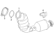
OEM Toyota Tundra Catalytic Converter
Cat. Converter- Select Vehicle by Model
- Select Vehicle by VIN
Select Vehicle by Model
orMake
Model
Year
Select Vehicle by VIN
For the most accurate results, select vehicle by your VIN (Vehicle Identification Number).
20 Catalytic Converters found


Toyota Tundra Front Pipe Part Number: 17410-0S070
$1589.67 MSRP: $2133.80You Save: $544.13 (26%)

Toyota Tundra Front Pipe Part Number: 17410-0S011
$1746.75 MSRP: $2344.65You Save: $597.90 (26%)
Toyota Tundra Front Pipe Part Number: 17410-0F050
$1495.81 MSRP: $2007.81You Save: $512.00 (26%)Ships in 1-3 Business Days
Toyota Tundra Exhaust Manifold, Passenger Side Part Number: 17104-38011
$416.99 MSRP: $611.10You Save: $194.11 (32%)Ships in 1-3 Business Days

Toyota Tundra Front Pipe Part Number: 17410-0S020
$1659.02 MSRP: $2226.88You Save: $567.86 (26%)Ships in 1-3 Business Days
Toyota Tundra Catalytic Converter, Driver Side Part Number: 17500-F4020
$1172.10 MSRP: $1717.73You Save: $545.63 (32%)Ships in 1-3 Business Days
Toyota Tundra Catalytic Converter, Passenger Side Part Number: 17400-F4020
$1183.68 MSRP: $1734.70You Save: $551.02 (32%)Ships in 1-3 Business Days
Toyota Tundra Exhaust Manifold, Passenger Side Part Number: 17140-31730
$279.04 MSRP: $398.40You Save: $119.36 (30%)Ships in 1-3 Business Days
Toyota Tundra Exhaust Manifold, Passenger Side Part Number: 17140-31170
$338.19 MSRP: $482.86You Save: $144.67 (30%)Ships in 1-3 Business DaysToyota Tundra Front Pipe Part Number: 17410-0F010
$1209.67 MSRP: $1623.73You Save: $414.06 (26%)Ships in 1-3 Business Days
Toyota Tundra Front Pipe Part Number: 17410-0S090
$1363.12 MSRP: $1829.71You Save: $466.59 (26%)Ships in 1-3 Business Days
Toyota Tundra Front Pipe Part Number: 17410-0P330
$1625.08 MSRP: $2181.33You Save: $556.25 (26%)Ships in 1-3 Business Days
Toyota Tundra Front Pipe Part Number: 17401-07050
$1733.52 MSRP: $2326.89You Save: $593.37 (26%)Ships in 1-3 Business Days
Toyota Tundra Front Pipe Part Number: 17410-0F090
$1934.48 MSRP: $2596.64You Save: $662.16 (26%)Ships in 1-3 Business Days

Toyota Tundra Front Pipe Part Number: 17410-0P170
$2183.50 MSRP: $2930.90You Save: $747.40 (26%)Ships in 1-3 Business Days
Toyota Tundra Front Pipe Part Number: 17410-0P010
$1201.61 MSRP: $1612.92You Save: $411.31 (26%)Ships in 1-3 Business Days
Toyota Tundra Front Pipe Part Number: 17410-0F030

Toyota Tundra Front Pipe Part Number: 17410-0P340
$1491.72 MSRP: $2002.32You Save: $510.60 (26%)Toyota Tundra Front Pipe Part Number: 17410-0S100
$1959.00 MSRP: $2629.55You Save: $670.55 (26%)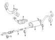
Toyota Tundra Catalytic Converter, Front Part Number: 17410-07041
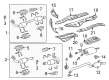
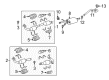
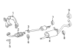
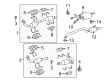
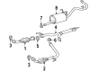
Toyota Tundra Catalytic Converter
Choose genuine Catalytic Converter that pass strict quality control tests. You can trust the top quality and lasting durability. Shopping for OEM Catalytic Converter for your Toyota Tundra? Our website is your one-stop destination. We stock an extensive selection of genuine Toyota Tundra parts. The price is affordable so you can save more. It only takes minutes to browse and find the exact fit. Easily add to cart and check out fast. Our hassle-free return policy will keep you stress-free. We process orders quickly for swift delivery. Your parts will arrive faster, so you can get back on the road sooner.
Another important part of the Toyota model is the Tundra Catalytic Converter's that bears the brunt of reducing some of the most dangerous toxic exhaust fumes into acceptable emissions. The destructive exhaust emission control system of the given car element uses redox reaction that cleans the toxic chemicals and produces water, oxygen and other low hazardous substances. Throughout the years, various kinds of Catalytic Converters have been installed in Tundra vehicles starting from the two-way then the three-way that also minimizes oxides of nitrogen. Such converters usually have ceramic honeycombs plated with platinum, palladium, and rhadium, and work only at the stoichiometric air-fuel ratio. Thus, the efficiency and durability of Toyota Tundra Catalytic Converter can be preserved through avoiding those risky driving behaviors and silicone sealing products. By application of these devices the auto industry has been able to exhibit considerable improvements in elimination of hazardous substances and environmental degradation.
Toyota Tundra Catalytic Converter Parts and Q&A
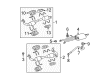
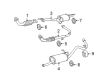
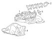
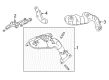
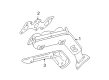
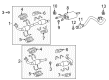
- Q: How to replace the catalytic converter on Toyota Tundra?A:The first step when replacing a catalytic converter involves disconnection of the heated Oxygen Sensor located at Bank 1. The exhaust center pipe requires removal of four bolts and two springs before continuation of the procedure. Begin by removing two nuts which secure the RH front Exhaust Pipe after which both gaskets on the RH front exhaust pipe and exhaust pipe need extraction. First disconnect Unit 2 heated oxygen sensor wiring connector and pull out the sensor from its position. The LH front exhaust pipe requires the removal of 2 nuts and the exhaust pipe support while dismantling the pipe completely together with its 2 gaskets. First disconnect A/F sensor connector for Bank 1 before you remove the 6 bolts and 2 manifold stays together with the sensor. Removing the Exhaust Manifold RH consists of uninstalling its 6 nuts and removing the manifold together with the gasket. Perform the same steps for the A/F sensor (Bank 2) while disconnecting its connector followed by removing the sensor. Then move to the exhaust manifold LH by taking off its 6 nuts and the manifold together with the gasket. Relay the exhaust manifold RH with a new gasket while placing the oval shape forward and torque all 6 nuts to 21 N.m (214 kgf.cm, 15 ft.lbf). Affix the Bank 1 A/F sensor by torqueing it to 44 N.m (450 kgf.cm, 33 ft.lbf) and attach its sensor connector. The LH exhaust manifold installation requires a new gasket oriented correctly facing backward and torqueing of 6 nuts to 21 N.m (214 kgf.cm, 15 ft.lbf). Fasten the A/F sensor for Bank 2 with 44 N.m (450 kgf.cm, 33 ft.lbf) torque while connecting its sensor connector. The two manifold stays should be installed with six bolts that receive torque to 40 N.m (408 kgf.cm, 30 ft.lbf). The LH front exhaust pipe installation requires 2 new gaskets before attaching with 2 new nuts and torqueing them to 62 N.m (630 kgf.cm, 46 ft.lbf) along with exhaust pipe support installation. Attach Bank 2 heated oxygen sensor while torquing the fastener to 44 N.m (450 kgf.cm, 33 ft.lbf) then link the sensor connector. Apply 2 new gaskets to the RH front exhaust pipe and fasten it with 2 new nuts tightened to 62 N.m (630 kgf.cm, 46 ft.lbf). At the end of the installation, secure the Bank 1 heated oxygen sensor with 44 N.m torque while connecting its sensor connector. Use 2 bolts to connect the exhaust center pipe while torqueing to 48 N.m (489 kgf.cm, 35 ft.lbf) and proceed to install 2 bolts with springs and torque them to 43 N.m (440 kgf.cm, 32 ft.lbf).

Related Toyota Tundra Parts
 Toyota Tundra Muffler
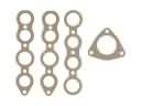 Toyota Tundra Exhaust Manifold
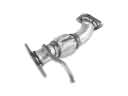 Toyota Tundra Exhaust Pipe
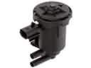 Toyota Tundra Canister Purge Valve
 Toyota Tundra Diverter Valve
 Toyota Tundra EGR Cooler
 Toyota Tundra EGR Valve
 Toyota Tundra EGR Valve Gasket
 Toyota Tundra Exhaust Flange Gasket
 Toyota Tundra Exhaust Hanger
 Toyota Tundra Exhaust Heat Shield
 Toyota Tundra Exhaust Manifold Gasket
Browse Toyota Tundra Catalytic Converter by Years
2025
2024
2023
2022
2021
2020
2019
2018
2017
2016
2015
2014
2013
2012
2011
2010
2009
2008
2007
2006
2005
2004
2003
2002
2001
2000