My Garage
Cart
Make sure this part fits

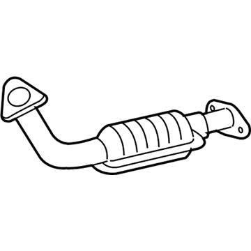
Toyota 17410-0F050
Front Pipe

2005-2006 Toyota Tundra 174100F050

Customer Questions & Expert Answers (3)
Toyota 17410-0F050 Front Pipe
  • Part Description
    Pipe Assembly, Exhaust; Catalytic Converter, Right; Exhaust Pipe
  • Part Name Code
    17410
  • Position
    Front
  • Manufacturer
    Toyota
Make sure this part fits
$1495.73 MSRP: $2007.70
You Save: $511.97 (26%)
Ships in 1-3 Business Days
1
ADD TO CART
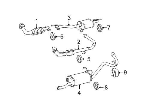
  • Related Parts
  • Product Specifications
  • Vehicle Fitment
  • Customer Questions & Expert Answers
  • Product Specifications

    BrandGenuine Toyota
    Part Name Code17410
    Manufacturer Part Number17410-0F050
    Part DescriptionPipe Assembly, Exhaust; Catalytic Converter, Right; Exhaust Pipe
    Other NamesPipe Assembly, Exhaust, Front
    Item Dimensions46.8 x 18.4 x 9.6 inches
    Item Weight11.70 Pounds
    PositionFront
    ConditionNew
    Fitment TypeDirect Replacement
    ManufacturerToyota
    SKU17410-0F050
    WarrantyThis genuine Toyota part is guaranteed by Toyota's factory warranty.
    Shipping & ReturnShipping Policy Return Policy
    Warning: California's Proposition 65
  • Vehicle Fitment

    Year Make Model Trim Engine
    2005-2006 Toyota TundraBase, Limited, SR58 Cyl 4.7 L GAS
  • Customer Questions & Expert Answers

    Q:
    Is 17410-0F050 a good match for my car? Posted by ToyotaPartsNow Specialist
    A:
    Find out if part number 17410-0F050 is the right fit for your car by Selecting Your Vehicle model.
    Posted by ToyotaPartsNow Specialist
    Q:
    How to replace the catalytic converter on Toyota Tundra? Posted by Customer
    A:
    The first step when replacing a catalytic converter involves disconnection of the heated oxygen sensor located at Bank 1. The exhaust center pipe requires removal of four bolts and two springs before continuation of the procedure. Begin by removing two nuts which secure the RH front exhaust pipe after which both gaskets on the RH front exhaust pipe and exhaust pipe need extraction. First disconnect Unit 2 heated oxygen sensor wiring connector and pull out the sensor from its position. The LH front exhaust pipe requires the removal of 2 nuts and the exhaust pipe support while dismantling the pipe completely together with its 2 gaskets. First disconnect A/F sensor connector for Bank 1 before you remove the 6 bolts and 2 manifold stays together with the sensor. Removing the exhaust manifold RH consists of uninstalling its 6 nuts and removing the manifold together with the gasket. Perform the same steps for the A/F sensor (Bank 2) while disconnecting its connector followed by removing the sensor. Then move to the exhaust manifold LH by taking off its 6 nuts and the manifold together with the gasket. Relay the exhaust manifold RH with a new gasket while placing the oval shape forward and torque all 6 nuts to 21 N.m (214 kgf.cm, 15 ft.lbf). Affix the Bank 1 A/F sensor by torqueing it to 44 N.m (450 kgf.cm, 33 ft.lbf) and attach its sensor connector. The LH exhaust manifold installation requires a new gasket oriented correctly facing backward and torqueing of 6 nuts to 21 N.m (214 kgf.cm, 15 ft.lbf). Fasten the A/F sensor for Bank 2 with 44 N.m (450 kgf.cm, 33 ft.lbf) torque while connecting its sensor connector. The two manifold stays should be installed with six bolts that receive torque to 40 N.m (408 kgf.cm, 30 ft.lbf). The LH front exhaust pipe installation requires 2 new gaskets before attaching with 2 new nuts and torqueing them to 62 N.m (630 kgf.cm, 46 ft.lbf) along with exhaust pipe support installation. Attach Bank 2 heated oxygen sensor while torquing the fastener to 44 N.m (450 kgf.cm, 33 ft.lbf) then link the sensor connector. Apply 2 new gaskets to the RH front exhaust pipe and fasten it with 2 new nuts tightened to 62 N.m (630 kgf.cm, 46 ft.lbf). At the end of the installation, secure the Bank 1 heated oxygen sensor with 44 N.m torque while connecting its sensor connector. Use 2 bolts to connect the exhaust center pipe while torqueing to 48 N.m (489 kgf.cm, 35 ft.lbf) and proceed to install 2 bolts with springs and torque them to 43 N.m (440 kgf.cm, 32 ft.lbf).
    Posted by ToyotaPartsNow Specialist
    Q:
    How to replace the catalytic converter on Toyota Tundra? Posted by Customer
    A:
    The heated oxygen sensor (Bank 1) needs removing as the first step in catalytic converter replacement. Unplug the sensor then take it off. The exhaust center pipe requires removal of its four bolts and two springs. Start by removing the RH front exhaust pipe through the procedure of removing its 2 nuts together with the pipe before eliminating the 2 gaskets. The procedure for Bank 2 heated oxygen sensor requires disconnecting its connector and sensor removal. To remove the LH front exhaust pipe you must first disconnect the two nuts and the exhaust pipe support before taking away the pipe and removing the two gaskets. Unbolt the manifold stay through the removal of all its six bolts and two support stays. Begin by disconnecting the A/F sensor (Bank 1) then proceed to remove the exhaust manifold RH by taking off all its 6 nuts along with the gasket. The installer should complete the same procedure for Bank 2 A/F sensor and exhaust manifold LH. Install the exhaust manifold RH by setting it with a new gasket, where the oval opening should point forward and apply 6 nuts evenly with 21 Nm of torque (214 kgf.cm, 15 ft.lbf). The A/F sensor (Bank 1) must be installed with 44 Nm (450 kgf.cm, 33 ft.lbf) torque before connecting its sensor connector. When installing the exhaust manifold LH, orient the new gasket with its oval shape positioned backward then fasten it with 6 nuts which should be tightened to 21 Nm (214 kgf.cm, 15 ft.lbf). The Bank 2 A/F sensor requires installation at 44 Nm torque (450 kgf.cm, 33 ft.lbf) while following up with the sensor connector connection. Screw the manifold stays into place with its 6 bolts and tighten them to 40 Nm (408 kgf.cm, 30 ft.lbf). The LH front exhaust pipe requires installation of new gaskets followed by the pipe and 2 new nuts which need a torque setting of 62 Nm (630 kgf.cm, 46 ft.lbf) before installing the exhaust pipe support. Tighten the heated oxygen sensor (Bank 2) to 44 Nm (450 kgf.cm, 33 ft.lbf) while connecting its sensor connector. The RH front exhaust pipe also requires 2 new gaskets with 2 new nuts that need to be torqued to 62 Nm (630 kgf.cm, 46 ft.lbf). Installing the heated oxygen sensor (Bank 1) requires a torque of 44 Nm (450 kgf.cm, 33 ft.lbf) followed by connecting the sensor connector and attaching the exhaust center pipe by setting 2 bolts to 48 Nm (489 kgf.cm, 35 ft.lbf) and using the 2 bolts and springs which need to be tightened to 43 Nm (440 kgf.cm, 32 ft.lbf).
    Posted by ToyotaPartsNow Specialist
    If you have any questions about this product, please don't hesitate to ask us. We will be happy to help you!

OEM Toyota 17410-0F050, Excellent Performance and Perfect Fitment

To ensure reliability, purchase Toyota part # 17410-0F050 Front Pipe. It is sometimes referred to as Toyota Catalytic Converter, Toyota Exhaust Pipe. OEM parts are unrivaled in terms of quality. They go through extensive quality control inspections and are produced in accordance with Toyota's official factory specifications. All of these remove defects and imperfections. So you can relax knowing they promise exceptional lifespan and flawless fitment.

ToyotaPartsNow.com is a leading supplier of genuine Toyota parts such as Toyota 174100F050 Front Pipe. At ToyotaPartsNow.com, we have a wide variety of OEM Toyota parts available at competitive prices. Our comprehensive range of genuine Toyota parts come with a manufacturer's warranty for peace of mind. We also prioritize customer satisfaction, providing a hassle-free return policy and expedited delivery for all our parts. For detailed Toyota parts information, click here.
Choose ToyotaPartsNow for discounted prices, exceptional service and fast delivery