×
ToyotaParts- Hello
- Login or Register
- Quick Links
- Live Chat
- Track Order
- Parts Availability
- RMA
- Help Center
- Contact Us
- Shop for
- Toyota Parts
- Scion Parts
My Garage
My Account
Cart
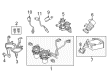
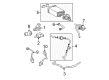
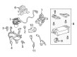
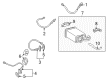
OEM Toyota Tundra Oxygen Sensor
Oxygen O2 Sensor- Select Vehicle by Model
- Select Vehicle by VIN
Select Vehicle by Model
orMake
Model
Year
Select Vehicle by VIN
For the most accurate results, select vehicle by your VIN (Vehicle Identification Number).
38 Oxygen Sensors found


Toyota Tundra Oxygen Sensor, Passenger Side Part Number: 89465-0C190
$125.71 MSRP: $177.96You Save: $52.25 (30%)Ships in 1-3 Business Days


Toyota Tundra Sensor, Air Fuel Ratio, Front Driver Side Part Number: 89467-04060
$194.31 MSRP: $277.43You Save: $83.12 (30%)Ships in 1-2 Business Days
Toyota Tundra Oxygen Sensor, Front Driver Side Part Number: 89467-04090
$192.10 MSRP: $274.27You Save: $82.17 (30%)Ships in 1-2 Business Days


Toyota Tundra Oxygen Sensor, Front Passenger Side Part Number: 89465-04300
$115.76 MSRP: $162.49You Save: $46.73 (29%)Ships in 1-2 Business Days

Toyota Tundra Oxygen Sensor, Passenger Side Part Number: 89467-0C050
$220.99 MSRP: $315.52You Save: $94.53 (30%)Ships in 1-2 Business Days


Toyota Tundra Oxygen Sensor, Driver Side Part Number: 89465-0C180
$122.19 MSRP: $172.97You Save: $50.78 (30%)Ships in 1-2 Business Days

Toyota Tundra Oxygen Sensor, Front Driver Side Part Number: 89465-0C140
$122.07 MSRP: $172.81You Save: $50.74 (30%)Ships in 1-3 Business Days

Toyota Tundra Oxygen Sensor, Rear Part Number: 89465-09320
$114.10 MSRP: $160.17You Save: $46.07 (29%)Ships in 1-2 Business Days

Toyota Tundra Oxygen Sensor, Rear Passenger Side Part Number: 89465-09310
$122.54 MSRP: $173.47You Save: $50.93 (30%)Ships in 1-3 Business Days

Toyota Tundra Oxygen Sensor Part Number: 89465-0C160
$127.36 MSRP: $180.29You Save: $52.93 (30%)Ships in 1-2 Business Days

Toyota Tundra Oxygen Sensor, Front Part Number: 89467-34021
$216.56 MSRP: $309.20You Save: $92.64 (30%)Ships in 1-2 Business Days


Toyota Tundra Oxygen Sensor Part Number: 89467-0C010
$219.82 MSRP: $313.86You Save: $94.04 (30%)Ships in 1-2 Business Days
Toyota Tundra Oxygen Sensor, Front Passenger Side Part Number: 89465-0C150
$110.31 MSRP: $154.85You Save: $44.54 (29%)Ships in 1-3 Business Days

Toyota Tundra Oxygen Sensor, Front Driver Side Part Number: 89467-0C060
$191.28 MSRP: $273.11You Save: $81.83 (30%)Ships in 1-2 Business Days

Toyota Tundra Oxygen Sensor, Front Part Number: 89467-34011
$228.91 MSRP: $326.83You Save: $97.92 (30%)Ships in 1-2 Business Days


Toyota Tundra Oxygen Sensor, Rear Driver Side Part Number: 89465-09300
$122.54 MSRP: $173.47You Save: $50.93 (30%)Ships in 1-3 Business Days

Toyota Tundra Oxygen Sensor, Passenger Side Part Number: 89465-0C300
$120.31 MSRP: $170.32You Save: $50.01 (30%)Ships in 1-3 Business Days


Toyota Tundra Oxygen Sensor, Front Driver Side Part Number: 89465-0C170
$128.06 MSRP: $181.29You Save: $53.23 (30%)Ships in 1-2 Business Days
Toyota Tundra Oxygen Sensor, Front Driver Side Part Number: 89465-34150
$136.52 MSRP: $193.27You Save: $56.75 (30%)Ships in 1-2 Business Days


Toyota Tundra Oxygen Sensor, Front Passenger Side Part Number: 89465-34140
$136.52 MSRP: $193.27You Save: $56.75 (30%)Ships in 1-2 Business Days
| Page 1 of 2 |Next >
1-20 of 38 Results
Toyota Tundra Oxygen Sensor
Choose genuine Oxygen Sensor that pass strict quality control tests. You can trust the top quality and lasting durability. Shopping for OEM Oxygen Sensor for your Toyota Tundra? Our website is your one-stop destination. We stock an extensive selection of genuine Toyota Tundra parts. The price is affordable so you can save more. It only takes minutes to browse and find the exact fit. Easily add to cart and check out fast. Our hassle-free return policy will keep you stress-free. We process orders quickly for swift delivery. Your parts will arrive faster, so you can get back on the road sooner.
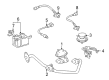
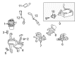
The Oxygen Sensor in Toyota Tundra is used to determine the amounts of oxygen in the exhaust system so that the engine computer can control the air to fuel ration for efficient burning of fuel. This process also optimise the fuel consumption and reduce exhaust fumes. Bad oxygen sensor can cause problems such as a weak idle, difficult start, higher fuel consumption, adverse effects on the performance and emissions from improved car fuel systems. Usually mounted on the passenger side, downstream of the catalytic converter, a Tundra may have multiple sensors depending on its exhaust setup. Single exhaust models come with a pair of sensors while the dual exhaust systems will come with four. Different kinds of oxygen sensors include the zirconia and titania sorts, that operate in different ways. Zirconia sensors are common used for feedback in the form of current values to sustain the proper air fuel mixture; titania sensors modulate the resistance instead of the voltage.
Toyota Tundra Oxygen Sensor Parts and Q&A
- Q: How to install an Oxygen Sensor in the Air Fuel Ratio Sensor and Exhaust Pipe Assemblies on Toyota Tundra?A:The installation of Air Fuel Ratio Sensor for Bank 1 Sensor 1 requires use of Special Service Tool: 09224-00010 along with a torque of 40 Nm (408 kgf-cm, 30 ft-lbf) for the tool or 44 Nm (449 kgf-cm, 32 ft-lbf) for the toolless method. This process requires a torque wrench with a fulcrum length of 30 cm (11.8 in.) and a straight line connection. Bank 2 Sensor 1 demands that you proceed with the same installation process and torque values. To begin with achining the Front Exhaust Pipe Assembly requires installation of a new gasket followed by 3 new nut attachment at 54 Nm (551 kgf-cm, 40 ft-lbf) to join the exhaust pipe to the Exhaust Manifold RH before linking the exhaust pipe to the center exhaust pipe with 2 bolts at 48 Nm (489 kgf-cm, 35 ft-lbf) while completing both air fuel ratio sensor and heated oxygen sensor connector connections. The Front No. 2 Exhaust Pipe Assembly (except Regular Cab Standard Deck) requires the exhaust pipe attachment to the support followed by installation of a new gasket to the exhaust manifold LH with 3 new nuts tightened to 54 Nm (551 kgf-cm, 40 ft-lbf) and final attachment to the center exhaust pipe using 2 bolts at 48 Nm (489 kgf-cm, 35 ft-lbf). The air fuel ratio sensor and heated oxygen sensor connectors must then be connected. When working on the Front No. 2 Exhaust Pipe Assembly of the Regular Cab Standard Deck the technician should install the new gasket at the exhaust manifold LH location using 54 Nm (551 kgf-cm, 40 ft-lbf) torque while also connecting the air fuel ratio sensor and heated oxygen sensor connectors. The Front No. 3 Exhaust Pipe Sub-Assembly installation for Regular Cab Standard Deck includes new gaskets applied to both front No. 2 and No. 3 exhaust pipes which are then bolted to the exhaust pipe support through 4 bolts and 2 new nuts at 48 Nm (489 kgf-cm, 35 ft-lbf). After disconnecting the cable from the negative battery terminal it is crucial to note that some systems request initialization steps before reconnecting the cable.
- Q: How to remove the heated oxygen sensors on Toyota Tundra?A:The first step for heated oxygen sensor removal from the 1GR-FE engine control system requires disconnecting the cable from the negative terminal then allowing a minimum of 90 seconds after switch-off to record memory and settings. The technician must start by taking off the front No. 3 Exhaust Pipe sub-assembly for Regular Cab Standard Deck before proceeding to remove the front No. 2 exhaust pipe assembly for Regular Cab Standard Deck then moving on to the front No. 2 exhaust pipe assembly for all other configurations. Move on to the subsequent step by taking out the front exhaust pipe assembly. To remove heated oxygen sensors from Bank 1 Sensor 2 and Bank 2 Sensor 2 use Special Service Tool: 09224-00010.


Related Toyota Tundra Parts
 Toyota Tundra Fuel Pump Relay
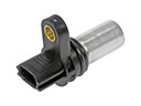 Toyota Tundra Camshaft Position Sensor
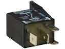 Toyota Tundra Headlight Relay
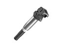 Toyota Tundra Ignition Coil
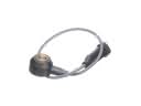 Toyota Tundra Knock Sensor
 Toyota Tundra Relay
 Toyota Tundra Spark Plug
 Toyota Tundra Engine Control Module
 Toyota Tundra Horn Relay
 Toyota Tundra Igniter
 Toyota Tundra Ignition Control Module
 Toyota Tundra Spark Plug Wire