×
ToyotaParts- Hello
- Login or Register
- Quick Links
- Live Chat
- Track Order
- Parts Availability
- RMA
- Help Center
- Contact Us
- Shop for
- Toyota Parts
- Scion Parts
My Garage
My Account
Cart
OEM Toyota Sequoia Parking Brake Cable
Emergency Parking Brake Release Cable- Select Vehicle by Model
- Select Vehicle by VIN
Select Vehicle by Model
orMake
Model
Year
Select Vehicle by VIN
For the most accurate results, select vehicle by your VIN (Vehicle Identification Number).
6 Parking Brake Cables found


Toyota Sequoia Rear Cable Part Number: 46430-0C030
$73.70 MSRP: $103.44You Save: $29.74 (29%)

Toyota Sequoia Rear Cable Part Number: 46420-0C080
$97.63 MSRP: $137.04You Save: $39.41 (29%)


Toyota Sequoia Rear Cable Part Number: 46420-34080
$118.37 MSRP: $166.15You Save: $47.78 (29%)Ships in 1-3 Business Days
Toyota Sequoia Front Cable Part Number: 46410-0C011
$57.83 MSRP: $80.49You Save: $22.66 (29%)Ships in 1-3 Business Days
Toyota Sequoia Rear Cable Part Number: 46430-34060
$70.85 MSRP: $99.45You Save: $28.60 (29%)Ships in 1-2 Business Days
Toyota Sequoia Front Cable Part Number: 46410-34150
$102.96 MSRP: $144.53You Save: $41.57 (29%)Ships in 1-3 Business Days
Toyota Sequoia Parking Brake Cable
Choose genuine Parking Brake Cable that pass strict quality control tests. You can trust the top quality and lasting durability. Shopping for OEM Parking Brake Cable for your Toyota Sequoia? Our website is your one-stop destination. We stock an extensive selection of genuine Toyota Sequoia parts. The price is affordable so you can save more. It only takes minutes to browse and find the exact fit. Easily add to cart and check out fast. Our hassle-free return policy will keep you stress-free. We process orders quickly for swift delivery. Your parts will arrive faster, so you can get back on the road sooner.
The Toyota Sequoia Parking Brake Cable is one of the most crucial parts of the Toyota Sequoia car since it enhances the parking brake thus allows for secure standing of the car especially on a given slope. This Parking Brake Cable is well known for its high Quality & excellent performance this cable acts as a link between the parking brake and the braking system of the vehicle which plays a vital role in minimizing the chances of any unexpected movement of the vehicle. Similar to many other car models, the Parking Brake Cable for Toyota Sequoia has gone through some generations while it remains as the same essential part but it may bear some unique characteristics to some models of the car. Maintenance of the Parking Brake Cable should be done often because stretching or wear is common and can cause the surface to engage insufficiently and therefore be unsafe. Failure of cable translates to total failure of parking brake and this means that Toyota Sequoia owners should be cautious. Where the Toyota Sequoia is concerned, it is a full-size SUV first launched in the year 2000 and has earned a good amount of esteem when it comes to its durability and capability The Parking Brake Cable here also operates with lots of efficiency. Besides, this cable also has its role to play in the overall safety of the vehicle and boosts inclination towards driving among the users. Some of the distinct characteristics of the Toyota Sequoia Parking Brake Cable include the following: It is sturdy and is able to operating under so much demand It is able to work with the two and four wheel drive Toyota Sequoia vehicles. In sum, the Toyota Sequoia Parking Brake Cable offers the automotive consumers durability, reliability, high-performance, and serves an exigent function in safeguarding the vehicle.
Toyota Sequoia Parking Brake Cable Parts and Q&A
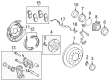
- Q: How to install the parking brake cable and related components on Toyota Sequoia?A:Begin the parking brake cable installation by inserting the parking brake shoe lever LH then apply the same procedure for installing the parking brake shoe lever RH on both sides. Begin the installation of the No. 2 parking brake shoe assembly by starting with the LH assembly before moving to the RH assembly. The installation process should be repeated exactly as performed for both sides. After installing the No. 1 parking brake shoe assembly LH you should install the matching RH assembly while keeping the procedures equal for each side of installation. The mechanics need to put in both parking brake shoe return springs LH and RH by performing the same installation procedure bilaterally. During installation of the rear disc LH followed by the rear disc RH both components require the same procedure on both sides to perform the check of the parking brake system. During the installation of the No. 3 parking brake cable assembly you should connect the inner cable end to the carrier assembly before tightening the bolt to 8.0 Nm (82 kgf-cm, 71 in-lbf). Pull and push the opposite end of the inner cable 2 or 3 times to verify proper cable seat within the guide spring while inspecting its connection through this movement. Attach the No. 3 parking brake cable to the rear axle carrier with one bolt while installing 4 bolts to the frame which should be tightened to 19 Nm (194 kgf-cm, 14 ft-lbf). When performing this task, avoid bending or twisting the cable. Sparely apply MP grease on the intermediate lever area where the cable meets then link the No. 3 parking brake cable to the intermediate lever. The assembly process for the No. 2 parking brake cable requires installation of the bolt to the rear axle carrier which should be torqued to 8.0 Nm (82 kgf-cm, 71 in-lbf) while using 8 bolts to connect the frame with a 19 Nm (194 kgf-cm, 14 ft-lbf) torque level before connecting it to the intermediate lever. The installation of the No. 2 cable retainer includes its bolt which needs to be torqued to 13 Nm (128 kgf-cm, 9 ft-lbf) along with the intermediate lever tension spring. Both rear disc brake cylinder assemblies LH and RH need the same installation procedure before installing rear wheels LH and RH simultaneously. The No. 1 parking brake cable assembly installation requires 2 bolts that need to be torqued to 5.4 Nm (55 kgf-cm, 48 in-lbf). The clamp must then be connected to the No. 1 parking brake cable before installing the clamp with its nut which requires the same torque value. The mechanic should install the No. 1 parking brake cable and cable retainer by securing the bolt with 13 Nm (128 kgf-cm, 9 ft-lbf) torque value before setting the adjustment nut and lock nut in place. He or she must note that final tightening of these nuts will happen according to specific torque values in the adjustment procedure. The technician will install both the front No. 2 Exhaust Pipe assembly for 3UR-FE and for 2UZ-FE and the front No. 3 exhaust pipe sub-assembly for 2UZ-FE. Settle the parking brake shoe while inspecting its disc before checking the parking brake pedal to make adjustments if needed. The installation process requires the No. 1 instrument panel safety pad insert and lower instrument panel finish panel sub-assembly LH, hood lock control lever sub-assembly and instrument side panel LH with cowl side trim board LH and front door scuff plate LH followed by exhaust gas leak inspection.
- Q: How to remove the parking brake cable on Toyota Sequoia?A:The first step to remove the parking brake cable requires removing front door scuff plate LH, cowl side trim board LH, instrument side panel LH, hood lock control lever sub-assembly, lower instrument panel finish panel sub-assembly LH, and No. 1 instrument panel safety pad insert. You should first release the parking brake pedal then unconnect the No. 1 parking brake cable assembly. During removal of the front No. 2 Exhaust Pipe assembly you should keep a 3UR-FE engine in mind while vehicles with 2UZ-FE engines require both exhaust pipe assemblies. The procedure requires removing the No. 1 parking brake cable assembly by first removing the adjustment nut and lock nut (labeled A) and then the bolt (labeled B) and cable retainer along with the nut (labeled C) and clamp from the body before disconnecting the clamp (labeled D) from the No. 1 parking brake cable. From inside the vehicle remove both bolts identified as E while taking out the No. 1 parking brake cable without bending or twisting the cable. Both rear wheels need to be orders off before proceeding with the right and left disc brake cylinder assembly removal via identical removal steps. The next step involves taking away the rear disc components LH and RH alongside using the earlier steps to handle both sides. Conceal the parking brake shoe return springs LH and RH. The following step involves removing the parking brake shoe assemblies No. 1 LH and RH along with No. 2 LH and RH using an identical method for each side. Start the removal by taking out the parking brake shoe levers plus the intermediate lever tension spring. Displacement of the No. 2 cable retainer requires detached bolt and cable retainer components. To detach the No. 3 parking brake cable assembly from the intermediate lever along with the removal of 4 bolts allows disconnection from the frame before cable removal while maintaining cable straightness before taking out the bolt and No. 3 parking brake cable from the rear axle carrier. The procedure for the No. 2 parking brake cable assembly includes disconnecting it from the intermediate lever while removing 8 bolts to detach from the frame and extracting bolt and cable from the rear axle carrier.


Related Toyota Sequoia Parts
 Toyota Sequoia Brake Pads
 Toyota Sequoia Brake Caliper
 Toyota Sequoia Brake Rotor
 Toyota Sequoia Wheel Bearing
 Toyota Sequoia Backing Plate
 Toyota Sequoia Brake Line
 Toyota Sequoia Brake Shoe Set
 Toyota Sequoia Hydraulic Hose
 Toyota Sequoia Parking Brake Shoes
 Toyota Sequoia Speed Sensor
 Toyota Sequoia Wheel Hub
 Toyota Sequoia Wheel Stud