×
ToyotaParts- Hello
- Login or Register
- Quick Links
- Live Chat
- Track Order
- Parts Availability
- RMA
- Help Center
- Contact Us
- Shop for
- Toyota Parts
- Scion Parts
My Garage
My Account
Cart
OEM Toyota Echo Brake Caliper
Caliper- Select Vehicle by Model
- Select Vehicle by VIN
Select Vehicle by Model
orMake
Model
Year
Select Vehicle by VIN
For the most accurate results, select vehicle by your VIN (Vehicle Identification Number).
4 Brake Calipers found


Toyota Echo Caliper, Driver Side Part Number: 47750-52010
$239.78 MSRP: $342.35You Save: $102.57 (30%)Ships in 1-3 Business Days
Toyota Echo Caliper, Passenger Side Part Number: 47730-52010
$239.78 MSRP: $342.35You Save: $102.57 (30%)Ships in 1-3 Business DaysToyota Echo Caliper, Driver Side Part Number: 47750-52020
$173.54 MSRP: $245.66You Save: $72.12 (30%)Ships in 1-3 Business DaysToyota Echo Caliper, Passenger Side Part Number: 47730-52020
$173.54 MSRP: $245.66You Save: $72.12 (30%)Ships in 1-3 Business Days
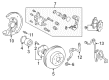
Toyota Echo Brake Caliper
Choose genuine Brake Caliper that pass strict quality control tests. You can trust the top quality and lasting durability. Shopping for OEM Brake Caliper for your Toyota Echo? Our website is your one-stop destination. We stock an extensive selection of genuine Toyota Echo parts. The price is affordable so you can save more. It only takes minutes to browse and find the exact fit. Easily add to cart and check out fast. Our hassle-free return policy will keep you stress-free. We process orders quickly for swift delivery. Your parts will arrive faster, so you can get back on the road sooner.
Toyota Echo Brake Caliper Parts and Q&A
- Q: How to service and repair the brake caliper on Toyota Echo?A:Service and repair of the brake caliper begins by using a screwdriver to remove set ring and cylinder boot. Position a cloth piece between the caliper and piston before you use compressed air to pull out the piston through the cylinder. Always avoid placing your fingers in front of the piston while working. The cylinder demands a screwdriver to eliminate its piston seal. Measuring pad lining thickness with a ruler must be done because standard is 11.0 mm (0.433 inch) but minimum stands at 1.0 mm (0.039 inch); replace pads when they reach minimum threshold or display severe pad damage. Use a micrometer to check the wheel disc thickness according to standard specifications which state 18.0 mm (0.709 in.) for a 13 inch disc and 16.0 mm (0.630 in.) for the same size and 20.0 mm (0.787 in.) for a 14 inch disc and 18.0 mm (0.709 in.) for this larger size. Disc replacement is required when minimum size is reached or wear damage exists. Measure the disc runout 10 mm from its outer edge using a dial indicator to check if maximum runout reaches 0.05 mm. Further investigation must address axial bearing play and axle hub runout to determine if disc adjustment or grinding is needed. The disc installation requires tilting it 1/4 turn from its original position before reattaching it to the hub while torquing the hub nuts to 88 Nm (900 kgf-cm, 65 ft. lbs.). Begin with bolt removal from the knuckle along with torque plate and hub nuts and disc. Reinstall the disc while checking its runout value until the minimum tolerance reaches below 0.05 mm (0.0020 inch); if this tolerance cannot be achieved, substitute the disc and measure its runout once more. Finishing the process includes putting back the torque plate and mounting bolts while torquing them to 88 Nm (900 kgf-cm, 65 ft. lbs.). The reinstallation proceeds with symmetric steps that start by reversing the order of disassembly steps while lubricating specific parts with lithium soap base glycol grease and disc brake grease.

Related Toyota Echo Parts
 Toyota Echo Brake Pads
 Toyota Echo Wheel Bearing
 Toyota Echo Brake Caliper Bracket
 Toyota Echo Brake Caliper Piston
 Toyota Echo Brake Drum
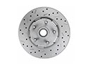 Toyota Echo Brake Rotor
 Toyota Echo Hydraulic Hose
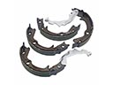 Toyota Echo Parking Brake Shoes
 Toyota Echo Speed Sensor
 Toyota Echo Spindle Nut
 Toyota Echo Wheel Hub
 Toyota Echo Wheel Stud