×
ToyotaParts- Hello
- Login or Register
- Quick Links
- Live Chat
- Track Order
- Parts Availability
- RMA
- Help Center
- Contact Us
- Shop for
- Toyota Parts
- Scion Parts
My Garage
My Account
Cart
OEM 2010 Scion xD PCV Valve
Position Crank Ventilation Valve- Select Vehicle by Model
- Select Vehicle by VIN
Select Vehicle by Model
orMake
Model
Year
Select Vehicle by VIN
For the most accurate results, select vehicle by your VIN (Vehicle Identification Number).
1 PCV Valve found


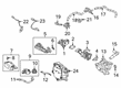
2010 Scion xD PCV Valve
Part Number: 12204-37010$6.08 MSRP: $8.46You Save: $2.38 (29%)Ships in 1-3 Business DaysProduct Specifications- Other Name: Valve Sub-Assembly, Vent; Engine Crankcase Vent Valve; Crankcase Vent Valve; Vent Valve; Valve Sub-Assembly, Ventilation
- Part Name Code: 12204
- Item Weight: 0.50 Pounds
- Item Dimensions: 2.2 x 1.1 x 0.9 inches
- Condition: New
- Fitment Type: Direct Replacement
- SKU: 12204-37010
- Warranty: This genuine part is guaranteed by Toyota's factory warranty.
2010 Scion xD PCV Valve
Looking for affordable OEM 2010 Scion xD PCV Valve? Explore our comprehensive catalogue of genuine 2010 Scion xD PCV Valve. All our parts are covered by the manufacturer's warranty. Plus, our straightforward return policy and speedy delivery service ensure an unparalleled shopping experience. We look forward to your visit!
2010 Scion xD PCV Valve Parts Q&A
- Q: How to remove the PCV Valve on 2010 Scion xD?A: The first step to remove the Positive Crankcase Ventilation Valve requires complete fuel system pressure discharge. Begin the process by detaching the negative battery cable before taking out both left and right engine under covers. The first step includes draining engine coolant then uninstalling the No. 2 cylinder head cover. First detach the air cleaner cap sub-assembly with its attached hose before separating the engine wire harness. Remove the harness bracket before taking off the No. 1 fuel vapor feed hose and No. 1 vacuum transmitting hose. The vacuum hose removal process requires the fuel pipe clamp removal and disconnection of the fuel tube sub-assembly. The technician must first remove the fuel delivery pipe sub-assembly followed by the sequence of removing the No.1 delivery pipe spacer then the injector vibration isolator. Guests should remove the starter assembly and the oil cooler tube for Automatic Transaxle use alongside the transmission oil level gauge sub-assembly for Automatic Transaxle. The technician must begin by disconnecting the ventilation valve sub-assembly only after removing both the engine oil level dipstick and the intake manifold and the ventilation hose.
Related 2010 Scion xD Parts
 2010 Scion xD Catalytic Converter
 2010 Scion xD Muffler
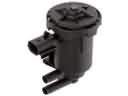 2010 Scion xD Canister Purge Valve
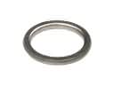 2010 Scion xD Exhaust Flange Gasket
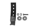 2010 Scion xD Exhaust Hanger
 2010 Scion xD Exhaust Heat Shield
 2010 Scion xD Exhaust Manifold
 2010 Scion xD Exhaust Manifold Gasket
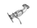 2010 Scion xD Exhaust Pipe
 2010 Scion xD Tail Pipe