×
ToyotaParts- Hello
- Login or Register
- Quick Links
- Live Chat
- Track Order
- Parts Availability
- RMA
- Help Center
- Contact Us
- Shop for
- Toyota Parts
- Scion Parts
My Garage
My Account
Cart
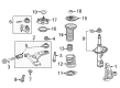
OEM 2010 Scion xB Control Arm
Suspension Arm- Select Vehicle by Model
- Select Vehicle by VIN
Select Vehicle by Model
orMake
Model
Year
Select Vehicle by VIN
For the most accurate results, select vehicle by your VIN (Vehicle Identification Number).
2 Control Arms found


2010 Scion xB Arm Sub-Assembly, Front Suspension, Lower Driver Side
Part Number: 48069-12300$168.48 MSRP: $238.50You Save: $70.02 (30%)Ships in 1-3 Business DaysProduct Specifications- Other Name: Arm Sub-Assembly, Suspension; Suspension Control Arm; Control Arm
- Position: Lower Driver Side
- Part Name Code: 48069
- Item Weight: 3.70 Pounds
- Item Dimensions: 22.8 x 3.6 x 16.6 inches
- Condition: New
- Fitment Type: Direct Replacement
- SKU: 48069-12300
- Warranty: This genuine part is guaranteed by Toyota's factory warranty.


2010 Scion xB Lower Control Arm, Passenger Side
Part Number: 48068-12300$159.08 MSRP: $225.20You Save: $66.12 (30%)Ships in 1-3 Business DaysProduct Specifications- Other Name: Arm Sub-Assembly, Suspension; Suspension Control Arm, Front Right; Control Arm Assembly; Arm Sub-Assembly, Front Suspension, Lower Passenger Side; Control Arm
- Position: Passenger Side
- Part Name Code: 48068
- Item Weight: 10.80 Pounds
- Item Dimensions: 23.0 x 3.6 x 17.8 inches
- Condition: New
- Fitment Type: Direct Replacement
- SKU: 48068-12300
- Warranty: This genuine part is guaranteed by Toyota's factory warranty.
2010 Scion xB Control Arm
Looking for affordable OEM 2010 Scion xB Control Arm? Explore our comprehensive catalogue of genuine 2010 Scion xB Control Arm. All our parts are covered by the manufacturer's warranty. Plus, our straightforward return policy and speedy delivery service ensure an unparalleled shopping experience. We look forward to your visit!
2010 Scion xB Control Arm Parts Q&A
- Q: How to remove the front lower Control Arm on 2010 Scion xB?A: Begin front lower suspension arm removal by taking off the wheels first followed by Engine Under Covers No. 1 and No. 2 and both rear engine under covers (left-hand and right-hand). The front lower No. 1 suspension arm sub-assemblies (LH and RH) require their bolts loosened without rotating the nuts since they include built-in stoppers. Follow the same procedure for both front lower No. 1 suspension arm sub-assemblies (LH and RH) by separating them. Detach the front suspension crossmember from the front lower No. 1 suspension arm sub-assembly (LH side) by removing its 2 bolts together with the nut according to specific instructions. After alignment set the front wheels straight ahead while the steering wheel remains fastened. To proceed remove the silencer sheet from the column hole and disassemble the intermediate shaft from No. 2 steering before removing the hole's No. 1 cover sub-assembly. The next step requires removing front stabilizer link assembly nuts on both LH and RH sides with the help of a 6mm hexagon wrench for ball joint nut mobility. Proceed with the separation of tie rod end sub-assemblies (LH and RH) through similarly applied methods for both directions simultaneously. The procedures begin with the removal of front suspension member reinforcements (LH and RH) through the extraction of their respective 4 bolts and continue with front suspension member brace rear (LH and RH) removal by dissolving 3 bolts from the LH side then repeating the same steps on the RH side. Support the front suspension crossmember by using a transmission jack before removing the 4 bolts, 2 nuts and front suspension crossmember sub-assembly for both manual and automatic transaxles followed by the removal of front lower No. 1 suspension arm sub-assemblies (LH and RH) from the front suspension crossmember keeping the nut attached.
Related 2010 Scion xB Parts
 2010 Scion xB Sway Bar Link
 2010 Scion xB Wheel Hub
 2010 Scion xB Ball Joint
 2010 Scion xB Bump Stop
 2010 Scion xB Coil Spring Insulator
 2010 Scion xB Shock Absorber
 2010 Scion xB Shock And Strut Mount
 2010 Scion xB Shock and Strut Boot
 2010 Scion xB Steering Knuckle
 2010 Scion xB Strut Housing
 2010 Scion xB Sway Bar Bushing
 2010 Scion xB Sway Bar Kit