×
ToyotaParts- Hello
- Login or Register
- Quick Links
- Live Chat
- Track Order
- Parts Availability
- RMA
- Help Center
- Contact Us
- Shop for
- Toyota Parts
- Scion Parts
My Garage
My Account
Cart
OEM 2009 Toyota Avalon Clock Spring
Spiral Cable Clock Spring- Select Vehicle by Model
- Select Vehicle by VIN
Select Vehicle by Model
orMake
Model
Year
Select Vehicle by VIN
For the most accurate results, select vehicle by your VIN (Vehicle Identification Number).
1 Clock Spring found


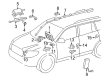
2009 Toyota Avalon Angle Sensor
Part Number: 84306-0E010$241.49 MSRP: $344.80You Save: $103.31 (30%)Ships in 1-3 Business DaysProduct Specifications- Other Name: Cable Sub-Assembly, Spiral; Steering Wheel Position Sensor; Air Bag Clockspring; Clockspring; Cable Sub-Assembly, Spiral W/Sensor
- Replaces: 84306-48030
- Item Weight: 3.10 Pounds
- Item Dimensions: 14.2 x 10.8 x 10.9 inches
- Condition: New
- Fitment Type: Direct Replacement
- SKU: 84306-0E010
- Warranty: This genuine part is guaranteed by Toyota's factory warranty.
2009 Toyota Avalon Clock Spring
Looking for affordable OEM 2009 Toyota Avalon Clock Spring? Explore our comprehensive catalogue of genuine 2009 Toyota Avalon Clock Spring. All our parts are covered by the manufacturer's warranty. Plus, our straightforward return policy and speedy delivery service ensure an unparalleled shopping experience. We look forward to your visit!
2009 Toyota Avalon Clock Spring Parts Q&A
- Q: How to install the Clock Spring Assembly / Spiral Cable on 2009 Toyota Avalon?A: Installation of the Clock Spring Assembly / Clock Spring begins by installing the steering angle sensor with VSC when both the front wheels remain straight and the turn signal switch occupies the neutral position to protect against pin snapping. To properly install the clock spring remove any lock pins being replaced after which connect the cable connectors while watching out for Air Bag wire harness damage. Continue by adding the steering column cover together with the lower steering column cover. When adjusting the clock spring disconnect the battery (-) terminal while the ignition remains switched off and wait at least 90 seconds before starting work. Begin by rotating the clock spring in the opposite direction until it becomes firm then continue rotation with clockwise movement of approximately 2.5 turns to achieve alignment using the manufacturer marks while maintaining a safe distance from the Air Bag wire harness. The next step requires installation of the steering wheel assembly and point-center assessment before attaching the steering pad together with lower steering wheel covers No.2 and No.3. The negative battery terminal cable must be restored before checking the steering pad and doing the initialization since some systems need such procedure after battery terminal removal. The final step is checking the SRS warning light for correct operation.
Related 2009 Toyota Avalon Parts
 2009 Toyota Avalon Ignition Switch
 2009 Toyota Avalon Air Bag Control Module
 2009 Toyota Avalon Air Bag Sensor
 2009 Toyota Avalon Brake Light Switch
 2009 Toyota Avalon Dimmer Switch
 2009 Toyota Avalon Door Jamb Switch
 2009 Toyota Avalon Ignition Lock Assembly
 2009 Toyota Avalon Mirror Switch
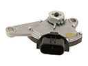 2009 Toyota Avalon Neutral Safety Switch
 2009 Toyota Avalon Relay
 2009 Toyota Avalon Speedometer
 2009 Toyota Avalon Turn Signal Flasher