×
ToyotaParts- Hello
- Login or Register
- Quick Links
- Live Chat
- Track Order
- Parts Availability
- RMA
- Help Center
- Contact Us
- Shop for
- Toyota Parts
- Scion Parts
My Garage
My Account
Cart
OEM 2009 Toyota Avalon Axle Shaft
Car Axle Shaft- Select Vehicle by Model
- Select Vehicle by VIN
Select Vehicle by Model
orMake
Model
Year
Select Vehicle by VIN
For the most accurate results, select vehicle by your VIN (Vehicle Identification Number).
2 Axle Shafts found


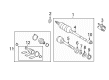
2009 Toyota Avalon Axle Assembly, Driver Side
Part Number: 43420-07080$299.92 MSRP: $454.74You Save: $154.82 (35%)Ships in 1-3 Business DaysProduct Specifications- Other Name: Shaft Assembly, Front Drive; CV Axle Assembly, Front Left; GSP Cv Axle; Axle Shaft; Shaft Assembly, Front Drive, Driver Side; CV Axle Assembly
- Position: Driver Side
- Part Name Code: 43420
- Item Weight: 15.10 Pounds
- Item Dimensions: 28.9 x 7.4 x 6.5 inches
- Condition: New
- Fitment Type: Direct Replacement
- SKU: 43420-07080
- Warranty: This genuine part is guaranteed by Toyota's factory warranty.
2009 Toyota Avalon Axle Assembly, Passenger Side
Part Number: 43410-07071$545.29 MSRP: $799.13You Save: $253.84 (32%)Product Specifications- Other Name: Shaft Assembly, Front Drive; CV Axle Assembly, Front Right; GSP Cv Axle; Axle Shaft; Shaft Assembly, Front Drive, Passenger Side; CV Axle Assembly
- Position: Passenger Side
- Replaces: 43410-07070
- Part Name Code: 43410
- Item Weight: 7.70 Pounds
- Item Dimensions: 28.9 x 7.5 x 6.4 inches
- Condition: New
- Fitment Type: Direct Replacement
- SKU: 43410-07071
- Warranty: This genuine part is guaranteed by Toyota's factory warranty.
2009 Toyota Avalon Axle Shaft
Looking for affordable OEM 2009 Toyota Avalon Axle Shaft? Explore our comprehensive catalogue of genuine 2009 Toyota Avalon Axle Shaft. All our parts are covered by the manufacturer's warranty. Plus, our straightforward return policy and speedy delivery service ensure an unparalleled shopping experience. We look forward to your visit!
2009 Toyota Avalon Axle Shaft Parts Q&A
- Q: How to install the axle shaft assembly LH and RH on 2009 Toyota Avalon?A: The installation of the LH front drive shaft assembly requires ATF lubrication of the inboard joint shaft assembly spline before alignment followed by brass-bar hammering from the side to ensure the snap ring opening points downwards and to prevent damage to the dust cover boot and oil seal as well as maintaining assembly level orientation. To install the front drive shaft assembly RH apply ATF to the spline then place the assembly while using a screwdriver to install a new bearing bracket hole snap ring with a torque of 32 Nm (330 kgf-cm, 24 ft-lbf) which should be carried out while avoiding boot and oil seal damage. Combine the matched positions on the front drive shaft assembly LH as you slot it against the front axle hub sub-assembly LH with precautions for boot and speed sensor rotor damage. Place the bolt and two nuts onto the front suspension arm sub-assembly lower No.1 LH lower ball joint before torquing it to 75 Nm (765 kgf-cm, 55 ft-lbf). To install the tie rod end sub-assembly LH on the steering knuckle use a nut which needs torquing to 49 Nm (500 kgf-cm, 36 ft-lbf) and follow by installing a new cotter pin then continuing to snug up the nut by up to 60 degrees if the holes show misalignment. After securing the front steering knuckle with a bolt torqued to 8.5 Nm (87 kgf-cm, 75 in-lbf), inspect for foreign matter on the sensor to prevent damage before attaching the flexible hose and speed sensor along with their bolt to the shock absorber with a proper sensor position on the knuckle using a torque of 19 Nm (192 kgf-cm, 14 ft-lbf). It is necessary to secure the front stabilizer link assembly LH by installing a nut that gets tightened to 74 Nm (755 kgf-cm, 55 ft-lbf). Keep the stud in place using a hexagon wrench (6 mm) to prevent the ball joint from turning while tightening the nut. A clean-up of the drive shaft and axle hub nut threads with non-residue solvent will be followed by a new axle hub LH nut installation using a 30 mm socket wrench to the specified torque of 294 Nm (3,000 kgf-cm, 217 ft-lbf). A chisel and hammer tool will be used to stake the nut. The front wheel installation requires 103 Nm of torque (1,050 kgf-cm and 76 ft-lbf), followed by automatic transaxle fluid addition and checking its state. Inspection of the front wheel alignment should be followed by installation of the engine under cover LH before testing speed sensor signals.
Related 2009 Toyota Avalon Parts
 2009 Toyota Avalon Control Arm
 2009 Toyota Avalon Lug Nuts
 2009 Toyota Avalon Bump Stop
 2009 Toyota Avalon CV Boot
 2009 Toyota Avalon Coil Spring Insulator
 2009 Toyota Avalon Coil Springs
 2009 Toyota Avalon Lateral Link
 2009 Toyota Avalon Shock And Strut Mount
 2009 Toyota Avalon Shock and Strut Boot
 2009 Toyota Avalon Strut Housing
 2009 Toyota Avalon Sway Bar Bracket
 2009 Toyota Avalon Transfer Case Output Shaft Snap Ring