×
ToyotaParts- Hello
- Login or Register
- Quick Links
- Live Chat
- Track Order
- Parts Availability
- RMA
- Help Center
- Contact Us
- Shop for
- Toyota Parts
- Scion Parts
My Garage
My Account
Cart
OEM 2008 Toyota Sequoia Timing Belt
Engine Timing Belt- Select Vehicle by Model
- Select Vehicle by VIN
Select Vehicle by Model
orMake
Model
Year
Select Vehicle by VIN
For the most accurate results, select vehicle by your VIN (Vehicle Identification Number).
1 Timing Belt found


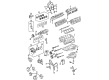
2008 Toyota Sequoia Belt, Timing
Part Number: 13568-09070$61.13 MSRP: $85.81You Save: $24.68 (29%)Ships in 1-3 Business DaysProduct Specifications- Other Name: Engine Timing Belt; Timing Belt Kit; Timing Belt
- Manufacturer Note: (L)
- Replaces: 13568-59095
- Part Name Code: 13568
- Item Weight: 2.40 Pounds
- Item Dimensions: 13.4 x 11.6 x 2.2 inches
- Condition: New
- Fitment Type: Direct Replacement
- SKU: 13568-09070
- Warranty: This genuine part is guaranteed by Toyota's factory warranty.
2008 Toyota Sequoia Timing Belt
Looking for affordable OEM 2008 Toyota Sequoia Timing Belt? Explore our comprehensive catalogue of genuine 2008 Toyota Sequoia Timing Belt. All our parts are covered by the manufacturer's warranty. Plus, our straightforward return policy and speedy delivery service ensure an unparalleled shopping experience. We look forward to your visit!
2008 Toyota Sequoia Timing Belt Parts Q&A
- Q: How to install the timing belt on 2008 Toyota Sequoia?A: The 2UZ-FE engine installation of the timing belt requires starting with the No. 2 timing belt idler sub-assembly and its bolt installation at 35 Nm (352 kgf-cm, 25 ft-lbf). Reusing the timing belt idler shaft requires Toyota Genuine Adhesive 1324 or its equivalent to be applied to 2 or 3 threads before installing the plate washer and idler with a bolt using a 10 mm hexagon wrench and torquing to 35 Nm (352 kgf-cm, 25 ft-lbf). To set the No. 1 cylinder at TDC/compression position use the camshaft hexagonal portion timing marks alignment while turning the crankshaft through the pulley set bolt alignment process. After cleaning the pulleys from water and oil residue, mount the belt with the front mark leading while positioning the timing marks directly facing one another. Use a handheld tool to push the push rod with a force of 981 to 9807 N (100 to 1000 kgf, 220.5 to 2204.7 lbf) for positioning both holes before fastening it with two bolts, which need tightening to 26 Nm (265 kgf-cm, 19 ft-lbf). The mechanics should check the No. 1 cylinder position at TDC/compression by applying clockwise pulley rotation twice while confirming mark alignment; reinstall the belt if the marks are not aligned. The work begins with installing the No. 1 crankshaft position sensor plate in its proper direction; this is followed by timing gear cover spacer with gasket before installing the No. 1 timing belt cover using four bolts that need 7.5 Nm (76 kgf-cm, 66 in-lbf) tightening force. The installation of the crankshaft pulley bolt requires Special Service Tool: 09213-70011 to stabilize the pulley as the operator torques the bolt to 245 Nm (2498 kgf-cm, 181 ft-lbf). The fan bracket installation requires two bolts and two nuts which must be torqued in this order: A and B to 16 Nm (163 kgf-cm, 12 ft-lbf) and C and D to 32 Nm (326 kgf-cm, 24 ft-lbf). Install the V-ribbed belt tensioner assembly through its bolt then fasten it with two nuts to 16 Nm (163 kgf-cm, 12 ft-lbf) torque. Fit the No. 2 timing belt cover sub-assembly to the claws then pins before tightening two bolts to 16 Nm (163 kgf-cm, 12 ft-lbf). The camshaft position sensor wire passes through the No. 3 timing belt cover sub-assembly LH hole before bolting up the cover with 4 fasteners set to a torque of 7.5 Nm (76 kgf-cm, 66 in-lbf). Sensor wire and engine wire clamps should be connected afterward. Proceed with sub-assembly installation of the No. 2 timing chain or belt cover by using 3 bolts and 1 nut and torquing them to 7.5 Nm (76 kgf-cm, 66 in-lbf). Fits the No. 2 idler pulley sub-assembly onto its cover plate then bolt it together before torquing it to 39 Nm (398 kgf-cm, 29 ft-lbf). After connecting the three water bypass hoses install together the oil cooler pipe by placing its cap nut and bolt which needs to be torqued to 7.5 Nm (76 kgf-cm, 66 in-lbf). The cooler compressor assembly installation requires 3 bolt torquing to 47 Nm (479 kgf-cm, 35 ft-lbf) combined with 25 Nm (255 kgf-cm, 18 ft-lbf) for the nut before connector attachment. The generator assembly should be installed along with the vane pump assembly using 2 bolts torqued to 28 Nm (286 kgf-cm, 21 ft-lbf) and the connector needs to be connected. The service procedure requires the installation of fan shroud followed by outlet and inlet radiator hoses and air cleaner assembly with the air cleaner hose and throttle body cover sub-assembly. Follow the procedure to check the coolant level and apply the engine coolant before installing the cable to the negative terminal of the battery at 5.4 Nm (55 kgf-cm, 48 in-lbf). Examine all components for leaks and inspect engine idle speed and ignition timing. The No. 1 engine under cover should be installed as the last step of the procedure.
Related 2008 Toyota Sequoia Parts
 2008 Toyota Sequoia Oil Filter
 2008 Toyota Sequoia Timing Chain
 2008 Toyota Sequoia Camshaft
 2008 Toyota Sequoia Crankshaft Gear
 2008 Toyota Sequoia Cylinder Head
 2008 Toyota Sequoia Dipstick Tube
 2008 Toyota Sequoia Intake Valve
 2008 Toyota Sequoia Piston
 2008 Toyota Sequoia Piston Ring Set
 2008 Toyota Sequoia Rod Bearing
 2008 Toyota Sequoia Timing Chain Tensioner
 2008 Toyota Sequoia Timing Cover