×
ToyotaParts- Hello
- Login or Register
- Quick Links
- Live Chat
- Track Order
- Parts Availability
- RMA
- Help Center
- Contact Us
- Shop for
- Toyota Parts
- Scion Parts
My Garage
My Account
Cart
OEM 2009 Toyota Sequoia Timing Belt
Engine Timing Belt- Select Vehicle by Model
- Select Vehicle by VIN
Select Vehicle by Model
orMake
Model
Year
Select Vehicle by VIN
For the most accurate results, select vehicle by your VIN (Vehicle Identification Number).
1 Timing Belt found


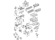
2009 Toyota Sequoia Belt, Timing
Part Number: 13568-09070$61.13 MSRP: $85.81You Save: $24.68 (29%)Ships in 1-3 Business DaysProduct Specifications- Other Name: Engine Timing Belt; Timing Belt Kit; Timing Belt
- Manufacturer Note: (L)
- Replaces: 13568-59095
- Part Name Code: 13568
- Item Weight: 2.40 Pounds
- Item Dimensions: 13.4 x 11.6 x 2.2 inches
- Condition: New
- Fitment Type: Direct Replacement
- SKU: 13568-09070
- Warranty: This genuine part is guaranteed by Toyota's factory warranty.
2009 Toyota Sequoia Timing Belt
Looking for affordable OEM 2009 Toyota Sequoia Timing Belt? Explore our comprehensive catalogue of genuine 2009 Toyota Sequoia Timing Belt. All our parts are covered by the manufacturer's warranty. Plus, our straightforward return policy and speedy delivery service ensure an unparalleled shopping experience. We look forward to your visit!
2009 Toyota Sequoia Timing Belt Parts Q&A
- Q: How to remove the timing belt on 2009 Toyota Sequoia?A: The first step to remove the 2UZ-FE engine timing belt requires disconnecting the negative terminal battery cable for at least 90 seconds to disable the SRS system. Now one must remove the No. 1 engine under cover followed by draining the engine coolant while also removing the throttle body cover sub-assembly. Begin by removing the air cleaner assembly together with its air cleaner hose before proceeding to take off the inlet and outlet radiator hoses. Direct the procedure to separate the fan shroud when a trailer towing system exists on the vehicle. The first step is to disconnect the connector and remove four fastenings including the 3 bolts, nut and No. 1 compressor stay from the cooler compressor assembly. The vane pump assembly requires both connector disconnection and bolt removal from two points. The next maintenance step involves taking out the generator assembly with the oil cooler pipe along with the No. 2 idler pulley sub-assembly and both timing belt covers of No. 2 and No. 3. Before removing the No. 3 timing belt cover, users should disconnect the camshaft position sensor connector along with the wire and remove the wire harness grommet from the path. The technician must use Special Service Tools: 09213-70011 09330-00021 and Special Service Tools: 09950-50013 09951-05010 to get rid of the V-ribbed belt tensioner assembly and fan bracket sub-assembly and crankshaft damper sub-assembly. The following sequence consists of clearing the No. 1 timing belt cover as well as timing gear cover spacer and No. 1 crankshaft position sensor plate. Place the pulley set bolt on the No. 1 cylinder temporarily and rotate the crankshaft clockwise to line up its timing marks at the compression position of TDC. The repair process requires the sequence of loosening alternate bolts and removing the timing belt tensioner and dust boot which results in timing belt removal before using a 10 mm hexagon wrench to take out the No. 1 and No. 2 timing belt idlers.
Related 2009 Toyota Sequoia Parts
 2009 Toyota Sequoia Oil Filter
 2009 Toyota Sequoia Timing Chain
 2009 Toyota Sequoia Camshaft
 2009 Toyota Sequoia Crankshaft Gear
 2009 Toyota Sequoia Cylinder Head
 2009 Toyota Sequoia Dipstick Tube
 2009 Toyota Sequoia Intake Valve
 2009 Toyota Sequoia Piston
 2009 Toyota Sequoia Piston Ring Set
 2009 Toyota Sequoia Rod Bearing
 2009 Toyota Sequoia Timing Chain Tensioner
 2009 Toyota Sequoia Timing Cover