×
ToyotaParts- Hello
- Login or Register
- Quick Links
- Live Chat
- Track Order
- Parts Availability
- RMA
- Help Center
- Contact Us
- Shop for
- Toyota Parts
- Scion Parts
My Garage
My Account
Cart
OEM 2008 Toyota Land Cruiser Air Bag Sensor
Air Bag Impact Sensor- Select Vehicle by Model
- Select Vehicle by VIN
Select Vehicle by Model
orMake
Model
Year
Select Vehicle by VIN
For the most accurate results, select vehicle by your VIN (Vehicle Identification Number).
6 Air Bag Sensors found


2008 Toyota Land Cruiser Side Impact Sensor, Front
Part Number: 89831-60010$85.27 MSRP: $102.81You Save: $17.54 (18%)Ships in 1-3 Business DaysProduct Specifications- Other Name: Sensor, Side Air Bag; Air Bag Impact Sensor, Front; Air Bag Sensor; Side Sensor; Sensor Assembly, Side Air Bag, Passenger Side; Sensor Assembly, Side Air Bag, Driver Side
- Position: Front
- Item Weight: 0.60 Pounds
- Item Dimensions: 4.3 x 2.7 x 2.1 inches
- Condition: New
- Fitment Type: Direct Replacement
- SKU: 89831-60010
- Warranty: This genuine part is guaranteed by Toyota's factory warranty.


2008 Toyota Land Cruiser Sensor, Air Bag, Front Passenger Side
Part Number: 89173-69205$86.14 MSRP: $103.86You Save: $17.72 (18%)Ships in 1-3 Business DaysProduct Specifications- Other Name: Sensor, Air Bag, Front; Sensor, Air Bag, Front Driver Side; Air Bag Sensor
- Position: Front
- Item Weight: 0.70 Pounds
- Item Dimensions: 4.7 x 3.0 x 2.4 inches
- Condition: New
- Fitment Type: Direct Replacement
- SKU: 89173-69205
- Warranty: This genuine part is guaranteed by Toyota's factory warranty.

2008 Toyota Land Cruiser Sensor, Rear Floor Side Air Bag
Part Number: 89837-60010$99.61 MSRP: $120.10You Save: $20.49 (18%)Ships in 1-3 Business DaysProduct Specifications- Other Name: Sensor, Floor Side Air Bag; Air Bag Sensor
- Part Name Code: 89837A
- Item Weight: 0.50 Pounds
- Condition: New
- Fitment Type: Direct Replacement
- SKU: 89837-60010
- Warranty: This genuine part is guaranteed by Toyota's factory warranty.

2008 Toyota Land Cruiser Sensor, Air Bag, Rear Passenger Side
Part Number: 89833-60040$123.81 MSRP: $175.27You Save: $51.46 (30%)Ships in 1-3 Business DaysProduct Specifications- Other Name: Sensor, Side Air Bag; Air Bag Sensor
- Position: Rear Passenger Side
- Part Name Code: 89833
- Item Weight: 0.60 Pounds
- Item Dimensions: 4.5 x 2.6 x 2.0 inches
- Condition: New
- Fitment Type: Direct Replacement
- SKU: 89833-60040
- Warranty: This genuine part is guaranteed by Toyota's factory warranty.
2008 Toyota Land Cruiser Sensor, Air Bag, Rear Driver Side
Part Number: 89831-60020$133.47 MSRP: $188.94You Save: $55.47 (30%)Ships in 1-3 Business DaysProduct Specifications- Other Name: Sensor, Side Air Bag; Air Bag Sensor
- Position: Rear Driver Side
- Part Name Code: 89834
- Item Weight: 0.60 Pounds
- Item Dimensions: 4.5 x 2.8 x 2.0 inches
- Condition: New
- Fitment Type: Direct Replacement
- SKU: 89831-60020
- Warranty: This genuine part is guaranteed by Toyota's factory warranty.

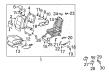
2008 Toyota Land Cruiser Position Sensor, Front Driver Side
Part Number: 89178-33050$89.81 MSRP: $126.06You Save: $36.25 (29%)Ships in 1-2 Business DaysProduct Specifications- Other Name: Sensor, Seat Position; Air Bag Seat Sensor Mat, Front Left; Seat Track Position Sensor, Left; Occupant Sensor; Passenger Discriminating Sensor; Discriminating Sensor; Sensor; Sensor, Seat Position Air Bag
- Position: Front Driver Side
- Part Name Code: 89178A
- Item Weight: 0.50 Pounds
- Item Dimensions: 2.1 x 1.6 x 1.3 inches
- Condition: New
- Fitment Type: Direct Replacement
- SKU: 89178-33050
- Warranty: This genuine part is guaranteed by Toyota's factory warranty.
2008 Toyota Land Cruiser Air Bag Sensor
Looking for affordable OEM 2008 Toyota Land Cruiser Air Bag Sensor? Explore our comprehensive catalogue of genuine 2008 Toyota Land Cruiser Air Bag Sensor. All our parts are covered by the manufacturer's warranty. Plus, our straightforward return policy and speedy delivery service ensure an unparalleled shopping experience. We look forward to your visit!
2008 Toyota Land Cruiser Air Bag Sensor Parts Q&A
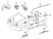
- Q: How to install the center Air Bag sensor assembly on 2008 Toyota Land Cruiser?A: The installation procedure for center Air Bag sensor assembly requires the engine switch to be off and negative cable disconnected from the battery terminal with minimum 90 seconds downtime to disable SRS system functions. Install the Air Bag sensor with 3 bolts applying 18 Nm torque amount (184 kgf-cm / 13 ft-lbf torque). Replacement of the center Air Bag sensor becomes necessary when it shows signs of drops or presents cracks or dents in any of its parts including the case, bracket, connector. Check SRS wiring and test for installation part looseness when installing the system while inspecting for possible part contact or pinching. Once the holder is connected it must have its connectors secured while verifying the waterproof sheet placement. The installation of front air conditioning units comes after. Complete your checks by connecting the cable to the negative battery terminal before verifying the SRS warning light works correctly.
Related 2008 Toyota Land Cruiser Parts
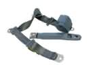 2008 Toyota Land Cruiser Seat Belt
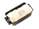 2008 Toyota Land Cruiser Air Bag
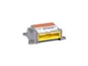 2008 Toyota Land Cruiser Air Bag Control Module
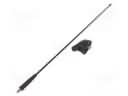 2008 Toyota Land Cruiser Antenna
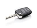 2008 Toyota Land Cruiser Car Key
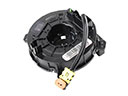 2008 Toyota Land Cruiser Clock Spring
 2008 Toyota Land Cruiser Coolant Temperature Sensor
 2008 Toyota Land Cruiser Daytime Running Light Relay
 2008 Toyota Land Cruiser Hazard Warning Switch
 2008 Toyota Land Cruiser Headlight Relay
 2008 Toyota Land Cruiser Knock Sensor
 2008 Toyota Land Cruiser Transmitter