×
ToyotaParts- Hello
- Login or Register
- Quick Links
- Live Chat
- Track Order
- Parts Availability
- RMA
- Help Center
- Contact Us
- Shop for
- Toyota Parts
- Scion Parts
My Garage
My Account
Cart
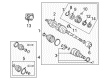
OEM 2008 Toyota Corolla Axle Shaft
Car Axle Shaft- Select Vehicle by Model
- Select Vehicle by VIN
Select Vehicle by Model
orMake
Model
Year
Select Vehicle by VIN
For the most accurate results, select vehicle by your VIN (Vehicle Identification Number).
8 Axle Shafts found

2008 Toyota Corolla Axle Assembly, Driver Side
Part Number: 43420-02360$387.70 MSRP: $568.18You Save: $180.48 (32%)Ships in 1-3 Business DaysProduct Specifications- Other Name: Shaft Assembly, Front Drive; CV Axle Assembly, Front Left; GSP Cv Axle; Axle Shaft; Shaft Assembly, Front Drive, Driver Side; CV Axle Assembly
- Position: Driver Side
- Part Name Code: 43420
- Item Weight: 14.60 Pounds
- Item Dimensions: 29.5 x 7.4 x 6.4 inches
- Condition: New
- Fitment Type: Direct Replacement
- SKU: 43420-02360
- Warranty: This genuine part is guaranteed by Toyota's factory warranty.
2008 Toyota Corolla Axle Assembly, Driver Side
Part Number: 43420-02320$404.05 MSRP: $592.14You Save: $188.09 (32%)Ships in 1-3 Business DaysProduct Specifications- Other Name: Shaft Assembly, Front Drive; CV Axle Assembly, Front Left; GSP Cv Axle; Axle Shaft; Shaft Assembly, Front Drive, Driver Side; CV Axle Assembly
- Manufacturer Note: W(ABS)
- Position: Driver Side
- Part Name Code: 43420
- Item Weight: 14.60 Pounds
- Item Dimensions: 30.4 x 7.3 x 6.7 inches
- Condition: New
- Fitment Type: Direct Replacement
- SKU: 43420-02320
- Warranty: This genuine part is guaranteed by Toyota's factory warranty.
- Product Specifications
- Other Name: Shaft Assembly, Front Drive; CV Axle Assembly, Front Right; GSP Cv Axle; Axle Shaft; Shaft Assembly, Front Drive, Passenger Side; CV Axle Assembly
- Manufacturer Note: W(ABS)
- Position: Passenger Side
- Part Name Code: 43410
- Item Weight: 14.90 Pounds
- Item Dimensions: 30.1 x 7.5 x 6.4 inches
- Condition: New
- Fitment Type: Direct Replacement
- SKU: 43410-02290
- Warranty: This genuine part is guaranteed by Toyota's factory warranty.
- Product Specifications
- Other Name: Shaft Assembly, Front Drive; CV Axle Assembly, Front Right; GSP Cv Axle; Axle Shaft; Axle; Shaft Assembly, Front Drive, Passenger Side; CV Axle Assembly
- Position: Passenger Side
- Part Name Code: 43410
- Item Weight: 17.70 Pounds
- Item Dimensions: 44.1 x 6.1 x 6.2 inches
- Condition: New
- Fitment Type: Direct Replacement
- SKU: 43410-02350
- Warranty: This genuine part is guaranteed by Toyota's factory warranty.
2008 Toyota Corolla Axle Assembly, Passenger Side
Part Number: 43410-02310$452.63 MSRP: $663.33You Save: $210.70 (32%)Product Specifications- Other Name: Shaft Assembly, Front Drive; CV Axle Assembly, Front Right; GSP Cv Axle; Axle Shaft; Axle; Shaft Assembly, Front Drive, Passenger Side; CV Axle Assembly
- Position: Passenger Side
- Part Name Code: 43410
- Item Weight: 20.20 Pounds
- Item Dimensions: 49.9 x 6.2 x 6.1 inches
- Condition: New
- Fitment Type: Direct Replacement
- SKU: 43410-02310
- Warranty: This genuine part is guaranteed by Toyota's factory warranty.
- Product Specifications
- Other Name: Shaft Assembly, Front Drive; CV Axle Assembly, Front Right; GSP Cv Axle; Axle Shaft; Shaft Assembly, Front Drive, Passenger Side; CV Axle Assembly
- Manufacturer Note: W(ABS)
- Position: Passenger Side
- Part Name Code: 43410
- Item Weight: 26.00 Pounds
- Item Dimensions: 44.1 x 5.5 x 5.4 inches
- Condition: New
- Fitment Type: Direct Replacement
- SKU: 43410-02330
- Warranty: This genuine part is guaranteed by Toyota's factory warranty.
- Product Specifications
- Other Name: Shaft Assembly, Front Drive; CV Axle Assembly, Front Left; GSP Cv Axle; Axle Shaft; Shaft Assembly, Front Drive, Driver Side; CV Axle Assembly
- Position: Driver Side
- Part Name Code: 43420
- Item Weight: 16.80 Pounds
- Item Dimensions: 30.1 x 5.2 x 5.3 inches
- Condition: New
- Fitment Type: Direct Replacement
- SKU: 43420-02380
- Warranty: This genuine part is guaranteed by Toyota's factory warranty.
- Product Specifications
- Other Name: Shaft Assembly, Front Drive; CV Axle Assembly, Front Left; GSP Cv Axle; Axle Shaft; Shaft Assembly, Front Drive, Driver Side; CV Axle Assembly
- Manufacturer Note: W(ABS)
- Position: Driver Side
- Part Name Code: 43420
- Item Weight: 17.60 Pounds
- Item Dimensions: 30.7 x 5.1 x 5.1 inches
- Condition: New
- Fitment Type: Direct Replacement
- SKU: 43420-02340
- Warranty: This genuine part is guaranteed by Toyota's factory warranty.
2008 Toyota Corolla Axle Shaft
Looking for affordable OEM 2008 Toyota Corolla Axle Shaft? Explore our comprehensive catalogue of genuine 2008 Toyota Corolla Axle Shaft. All our parts are covered by the manufacturer's warranty. Plus, our straightforward return policy and speedy delivery service ensure an unparalleled shopping experience. We look forward to your visit!
2008 Toyota Corolla Axle Shaft Parts Q&A
- Q: How to reassemble the axle shaft on 2008 Toyota Corolla?A: Installation of the dust cover LH begins with Special Service Tool: 09527-10011 and a press to install it properly without damaging the component. Install the dust cover on the right-hand side through the same method. Start by placing the new LH hole snap ring before you secure the drive shaft in aluminum plates within a vise. Cover the spline with vinyl tape for protection before installing the outboard joint boots. Install two clamps onto a new outboard joint boot before filling the boot and outboard joint shaft with grease to 135 to 155 g (4.8 to 5.5 oz). Afterwards apply the outboard joint boot clamps. Special Service Tool 09521-24010 should be used to pinch the clamps while Special Service Tool 09240-00020 is utilized to measure the clearance at 1.4 to 2.1 mm (0.0551 to 0.0826 in.) for the first clamp and 1.2 to 2.6 mm (0.0472 to 0.1023 in.) for the second clamp. To test the RH drive shaft damper distance secure the clamp then measure the clearance that should not exceed 1.5 mm (0.059 inches). To install the front axle inboard joint sub-assembly LH you should wrap the spline with vinyl tape before adding the inboard joint boot LH clamp, inboard joint boot, and inboard joint boot LH No. 2 clamp followed by installation of the new inner LH shaft snap ring. The correct orientation of the tripod joint assembly can be achieved by using a brass bar alongside a hammer during installation. Apply grease into the inboard joint sub-assembly LH and follow by mounting it to the outboard joint shaft assembly. Install the inboard joint boot before using Special Service Tool: 09521-24010 to secure the front axle inboard joint boot LH clamp. Check the clearance measurement because it should not exceed 1.5 mm (0.059 in.). Through the use of needle nose pliers attach No. 2 front axle inboard joint boot LH No. 2 clamp while inspecting the front drive shaft assembly LH.
Related 2008 Toyota Corolla Parts
 2008 Toyota Corolla CV Joint
 2008 Toyota Corolla CV Boot
 2008 Toyota Corolla Control Arm Bushing
 2008 Toyota Corolla Shock Absorber
 2008 Toyota Corolla Steering Knuckle
 2008 Toyota Corolla Axle Beam Mount
 2008 Toyota Corolla Bump Stop
 2008 Toyota Corolla Coil Spring Insulator
 2008 Toyota Corolla Shock And Strut Mount
 2008 Toyota Corolla Sway Bar Bracket
 2008 Toyota Corolla Sway Bar Bushing
 2008 Toyota Corolla Sway Bar Kit