×
ToyotaParts- Hello
- Login or Register
- Quick Links
- Live Chat
- Track Order
- Parts Availability
- RMA
- Help Center
- Contact Us
- Shop for
- Toyota Parts
- Scion Parts
My Garage
My Account
Cart
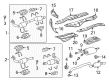
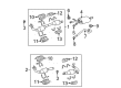
OEM 2007 Toyota Tundra Exhaust Pipe
Exhaust Tail Pipe- Select Vehicle by Model
- Select Vehicle by VIN
Select Vehicle by Model
orMake
Model
Year
Select Vehicle by VIN
For the most accurate results, select vehicle by your VIN (Vehicle Identification Number).
18 Exhaust Pipes found


2007 Toyota Tundra Front Pipe
Part Number: 17410-0S070$1589.67 MSRP: $2133.80You Save: $544.13 (26%)Product Specifications- Other Name: Pipe Assembly, Exhaust; Catalytic Converter, Right; Exhaust Pipe; Pipe Assembly, Exhaust, Front
- Position: Front
- Part Name Code: 17410
- Item Weight: 13.10 Pounds
- Condition: New
- Fitment Type: Direct Replacement
- SKU: 17410-0S070
- Warranty: This genuine part is guaranteed by Toyota's factory warranty.

2007 Toyota Tundra Front Pipe, Driver Side
Part Number: 17450-0S140$1846.75 MSRP: $2478.87You Save: $632.12 (26%)Ships in 1-3 Business DaysProduct Specifications- Other Name: Pipe Assembly, Exhaust Front; Catalytic Converter, Left; Exhaust Pipe; Pipe Assembly, Exhaust, Front
- Position: Front Driver Side
- Replaces: 17450-0S011, 17450-0S010
- Part Name Code: 17450B
- Item Weight: 6.30 Pounds
- Condition: New
- Fitment Type: Direct Replacement
- SKU: 17450-0S140
- Warranty: This genuine part is guaranteed by Toyota's factory warranty.

2007 Toyota Tundra Front Pipe, Driver Side
Part Number: 17450-0S200$1432.59 MSRP: $1922.94You Save: $490.35 (26%)Ships in 1-3 Business DaysProduct Specifications- Other Name: Pipe Assembly, Exhaust Front; Catalytic Converter; Exhaust Pipe; Pipe Assembly, Exhaust, Front
- Position: Front Driver Side
- Replaces: 17450-0S021, 17450-0S170, 17450-0S020
- Part Name Code: 17450B
- Item Weight: 14.00 Pounds
- Condition: New
- Fitment Type: Direct Replacement
- SKU: 17450-0S200
- Warranty: This genuine part is guaranteed by Toyota's factory warranty.

2007 Toyota Tundra Front Pipe, Driver Side
Part Number: 17450-0S190$1432.59 MSRP: $1922.94You Save: $490.35 (26%)Product Specifications- Other Name: Pipe Assembly, Exhaust Front; Catalytic Converter; Exhaust Pipe; Pipe Assembly, Exhaust, Front
- Position: Front Driver Side
- Replaces: 17450-0S030, 17450-0S160, 17450-0S031
- Part Name Code: 17450B
- Item Weight: 16.70 Pounds
- Condition: New
- Fitment Type: Direct Replacement
- SKU: 17450-0S190
- Warranty: This genuine part is guaranteed by Toyota's factory warranty.

2007 Toyota Tundra Muffler & Pipe, Center
Part Number: 17420-0F041$661.47 MSRP: $887.88You Save: $226.41 (26%)Ships in 1-3 Business DaysProduct Specifications- Other Name: Pipe Assembly, Exhaust; Muffler Assembly; Direct-Fit Exhaust; System Kit; Tail Pipe; Muffler; Pipe Assembly, Exhaust, Center
- Position: Center
- Replaces: 17420-0F040
- Part Name Code: 17420
- Item Weight: 16.90 Pounds
- Item Dimensions: 52.4 x 19.8 x 9.0 inches
- Condition: New
- Fitment Type: Direct Replacement
- SKU: 17420-0F041
- Warranty: This genuine part is guaranteed by Toyota's factory warranty.

2007 Toyota Tundra Tail Pipe
Part Number: 17430-0S010$319.20 MSRP: $417.43You Save: $98.23 (24%)Ships in 1-3 Business DaysProduct Specifications- Other Name: Pipe Assembly, Exhaust Tail; Exhaust Tail Pipe; Direct-Fit Exhaust; Exhaust System Kit; Exhaust Pipe; Tailpipe; Pipe Assembly, Exhaust, Tail
- Part Name Code: 17430
- Item Weight: 10.20 Pounds
- Item Dimensions: 43.6 x 12.5 x 9.1 inches
- Condition: New
- Fitment Type: Direct Replacement
- SKU: 17430-0S010
- Warranty: This genuine part is guaranteed by Toyota's factory warranty.

2007 Toyota Tundra Tail Pipe
Part Number: 17430-0F010$255.59 MSRP: $334.25You Save: $78.66 (24%)Ships in 1-3 Business DaysProduct Specifications- Other Name: Pipe Assembly, Exhaust Tail; Exhaust Tail Pipe; Exhaust Pipe; Direct-Fit Exhaust; Exhaust System Kit; Tailpipe; Pipe Assembly, Exhaust, Tail
- Part Name Code: 17430
- Item Weight: 10.30 Pounds
- Item Dimensions: 43.6 x 12.5 x 8.8 inches
- Condition: New
- Fitment Type: Direct Replacement
- SKU: 17430-0F010
- Warranty: This genuine part is guaranteed by Toyota's factory warranty.

2007 Toyota Tundra Front Pipe, Driver Side
Part Number: 17450-0P110$2798.10 MSRP: $3755.87You Save: $957.77 (26%)Ships in 1-3 Business DaysProduct Specifications- Other Name: Pipe Assembly, Exhaust Front; Catalytic Converter; Exhaust Pipe; Pipe Assembly, Exhaust, Front
- Position: Front Driver Side
- Part Name Code: 17450B
- Item Weight: 14.90 Pounds
- Item Dimensions: 39.6 x 13.7 x 8.5 inches
- Condition: New
- Fitment Type: Direct Replacement
- SKU: 17450-0P110
- Warranty: This genuine part is guaranteed by Toyota's factory warranty.

2007 Toyota Tundra Front Pipe, Driver Side
Part Number: 17450-0P120$2244.68 MSRP: $3013.01You Save: $768.33 (26%)Ships in 1-3 Business DaysProduct Specifications- Other Name: Pipe Assembly, Exhaust Front; Catalytic Converter; Exhaust Pipe; Pipe Assembly, Exhaust, Front
- Position: Front Driver Side
- Part Name Code: 17450B
- Item Weight: 11.00 Pounds
- Item Dimensions: 40.8 x 14.4 x 8.5 inches
- Condition: New
- Fitment Type: Direct Replacement
- SKU: 17450-0P120
- Warranty: This genuine part is guaranteed by Toyota's factory warranty.

2007 Toyota Tundra Front Pipe
Part Number: 17410-0P170$2183.50 MSRP: $2930.90You Save: $747.40 (26%)Ships in 1-3 Business DaysProduct Specifications- Other Name: Pipe Assembly, Exhaust; Catalytic Converter; Exhaust Pipe; Pipe Assembly, Exhaust, Front
- Position: Front
- Part Name Code: 17410
- Item Weight: 11.20 Pounds
- Item Dimensions: 47.7 x 18.0 x 9.3 inches
- Condition: New
- Fitment Type: Direct Replacement
- SKU: 17410-0P170
- Warranty: This genuine part is guaranteed by Toyota's factory warranty.

2007 Toyota Tundra Front Pipe, Driver Side
Part Number: 17450-0F120$1849.58 MSRP: $2482.68You Save: $633.10 (26%)Ships in 1-3 Business DaysProduct Specifications- Other Name: Pipe Assembly, Exhaust Front; Catalytic Converter, Left; Exhaust Pipe; Pipe Assembly, Exhaust, Front
- Position: Front Driver Side
- Part Name Code: 17450B
- Item Weight: 11.20 Pounds
- Item Dimensions: 40.8 x 14.4 x 8.7 inches
- Condition: New
- Fitment Type: Direct Replacement
- SKU: 17450-0F120
- Warranty: This genuine part is guaranteed by Toyota's factory warranty.

2007 Toyota Tundra Front Pipe, Driver Side
Part Number: 17450-0F130$1987.60 MSRP: $2667.94You Save: $680.34 (26%)Ships in 1-3 Business DaysProduct Specifications- Other Name: Pipe Assembly, Exhaust Front; Catalytic Converter; Exhaust Pipe; Pipe Assembly, Exhaust, Front
- Position: Front Driver Side
- Part Name Code: 17450B
- Item Weight: 11.00 Pounds
- Item Dimensions: 40.0 x 14.4 x 8.5 inches
- Condition: New
- Fitment Type: Direct Replacement
- SKU: 17450-0F130
- Warranty: This genuine part is guaranteed by Toyota's factory warranty.

2007 Toyota Tundra Front Pipe
Part Number: 17410-0F090$1934.48 MSRP: $2596.64You Save: $662.16 (26%)Ships in 1-3 Business DaysProduct Specifications- Other Name: Pipe Assembly, Exhaust; Catalytic Converter, Right; Exhaust Pipe; Pipe Assembly, Exhaust, Front
- Position: Front
- Part Name Code: 17410
- Item Weight: 11.00 Pounds
- Item Dimensions: 48.6 x 17.7 x 9.5 inches
- Condition: New
- Fitment Type: Direct Replacement
- SKU: 17410-0F090
- Warranty: This genuine part is guaranteed by Toyota's factory warranty.

2007 Toyota Tundra Muffler & Pipe, Center
Part Number: 17420-0S021$710.16 MSRP: $953.24You Save: $243.08 (26%)Ships in 1-3 Business DaysProduct Specifications- Other Name: Pipe Assembly, Exhaust; Muffler Assembly; Direct-Fit Exhaust; System Kit; Tail Pipe; Muffler; Pipe Assembly, Exhaust, Center
- Position: Center
- Replaces: 17420-0S020
- Part Name Code: 17420
- Item Weight: 16.90 Pounds
- Item Dimensions: 51.4 x 19.8 x 9.3 inches
- Condition: New
- Fitment Type: Direct Replacement
- SKU: 17420-0S021
- Warranty: This genuine part is guaranteed by Toyota's factory warranty.

2007 Toyota Tundra Muffler & Pipe, Center
Part Number: 17420-0F050$710.16 MSRP: $953.24You Save: $243.08 (26%)Ships in 1-3 Business DaysProduct Specifications- Other Name: Pipe Assembly, Exhaust; Exhaust Muffler; Exhaust Pipe; Tail Pipe; Muffler; Pipe Assembly, Exhaust, Center
- Position: Center
- Part Name Code: 17420
- Item Weight: 16.80 Pounds
- Item Dimensions: 52.4 x 19.6 x 9.0 inches
- Condition: New
- Fitment Type: Direct Replacement
- SKU: 17420-0F050
- Warranty: This genuine part is guaranteed by Toyota's factory warranty.

2007 Toyota Tundra Muffler & Pipe, Center
Part Number: 17420-0S030$659.42 MSRP: $885.14You Save: $225.72 (26%)Ships in 1-3 Business DaysProduct Specifications- Other Name: Pipe Assembly, Exhaust; Exhaust Muffler; Exhaust Muffler Assembly; Exhaust Pipe; Tail Pipe; Muffler; Pipe Assembly, Exhaust, Center
- Position: Center
- Part Name Code: 17420
- Item Weight: 16.30 Pounds
- Item Dimensions: 50.9 x 19.6 x 9.1 inches
- Condition: New
- Fitment Type: Direct Replacement
- SKU: 17420-0S030
- Warranty: This genuine part is guaranteed by Toyota's factory warranty.

2007 Toyota Tundra Muffler & Pipe, Center
Part Number: 17420-0S010$610.85 MSRP: $819.93You Save: $209.08 (26%)Ships in 1-3 Business DaysProduct Specifications- Other Name: Pipe Assembly, Exhaust; Exhaust Muffler; Exhaust Pipe; Tail Pipe; Muffler; Pipe Assembly, Exhaust, Center
- Position: Center
- Part Name Code: 17420
- Item Weight: 17.10 Pounds
- Item Dimensions: 50.4 x 19.5 x 9.3 inches
- Condition: New
- Fitment Type: Direct Replacement
- SKU: 17420-0S010
- Warranty: This genuine part is guaranteed by Toyota's factory warranty.

2007 Toyota Tundra Muffler & Pipe, Center
Part Number: 17420-0F030$485.20 MSRP: $651.28You Save: $166.08 (26%)Ships in 1-3 Business DaysProduct Specifications- Other Name: Pipe Assembly, Exhaust; Exhaust Muffler; Exhaust Pipe; Tail Pipe; Muffler; Pipe Assembly, Exhaust, Center
- Position: Center
- Part Name Code: 17420
- Item Weight: 16.80 Pounds
- Item Dimensions: 51.4 x 19.8 x 9.2 inches
- Condition: New
- Fitment Type: Direct Replacement
- SKU: 17420-0F030
- Warranty: This genuine part is guaranteed by Toyota's factory warranty.
2007 Toyota Tundra Exhaust Pipe
Looking for affordable OEM 2007 Toyota Tundra Exhaust Pipe? Explore our comprehensive catalogue of genuine 2007 Toyota Tundra Exhaust Pipe. All our parts are covered by the manufacturer's warranty. Plus, our straightforward return policy and speedy delivery service ensure an unparalleled shopping experience. We look forward to your visit!
2007 Toyota Tundra Exhaust Pipe Parts Q&A
- Q: How to service and repair the exhaust pipe on 2007 Toyota Tundra?A: The procedure to maintain the exhaust pipe (excluding Regular Cab Standard Deck) begins by utilizing protective gloves when dealing with the pipe after it reaches sufficient cooling temperature. Start by taking off the bolt and clamp securing the tailpipe before disconnecting it from the exhaust pipe support. The 4 bolts connecting the center exhaust pipe assembly must be unscrewed before disconnecting the entire assembly from its position on the 3 exhaust pipe supports. To remove the front No. 2 exhaust pipe assembly start by disconnecting both air fuel ratio sensor and heated oxygen sensor connectors followed by removing 3 nuts to detach it from the exhaust pipe support. Follow the same procedure for the front exhaust pipe assembly which involves cutting connections of the air fuel ratio sensor and heated oxygen sensor connectors while detaching both heated oxygen sensor wire clamps and removing three nuts. Move on to disconnect the Bank 1 Sensor 1 and Bank 2 Sensor 1 air fuel ratio sensors together with removing the Bank 1 Sensor 2 and Bank 2 Sensor 2 heated oxygen sensors from the vehicle. The installation order begins with Bank 1 Sensor 1 and Bank 2 Sensor 1 air fuel ratio sensors followed by Bank 1 Sensor 2 and Bank 2 Sensor 2 heated oxygen sensors. Reinstall the front exhaust pipe assembly after attaching it to exhaust manifold RH through new gaskets installed with 3 new nuts tightened to 54 N m (554 kgf cm, 40 ft. lbf). Finally, restore connections of air fuel ratio sensor and heated oxygen sensor while attaching the 2 heated oxygen sensor wire clamps. The installation continues with front No. 2 exhaust pipe attachment to the exhaust pipe support using new gaskets before 3 new nuts are applied to exhaust manifold LH while torquing them to 54 N m (554 kgf cm, 40 ft. lbf) before air fuel ratio and heated oxygen sensor connectors are reattached. The center exhaust pipe assembly requires installation between 3 exhaust pipe supports while adding 2 new gaskets to the front exhaust pipe LH and RH before attaching it with 4 bolts torqued to 48 N m (489 kgf cm, 35 ft. lbf). Install the tailpipe assembly by attaching it to the exhaust pipe support while using a new gasket near the center pipe and securing it with a new clamp that meets 32 N m (326 kgf cm, 24 ft. lbf) torque and aligning within the indicated angle range before exhaust gas leak inspection.
Related 2007 Toyota Tundra Parts
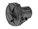 2007 Toyota Tundra Air Injection Pump
 2007 Toyota Tundra Catalytic Converter
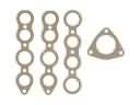 2007 Toyota Tundra Exhaust Manifold
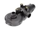 2007 Toyota Tundra PCV Valve
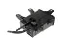 2007 Toyota Tundra Vapor Canister
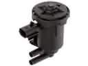 2007 Toyota Tundra Canister Purge Valve
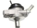 2007 Toyota Tundra Diverter Valve
 2007 Toyota Tundra EGR Valve Gasket
 2007 Toyota Tundra Exhaust Flange Gasket
 2007 Toyota Tundra Exhaust Hanger
 2007 Toyota Tundra Exhaust Heat Shield
 2007 Toyota Tundra Exhaust Manifold Gasket