×
ToyotaParts- Hello
- Login or Register
- Quick Links
- Live Chat
- Track Order
- Parts Availability
- RMA
- Help Center
- Contact Us
- Shop for
- Toyota Parts
- Scion Parts
My Garage
My Account
Cart
OEM 2007 Toyota Prius Parking Brake Cable
Emergency Parking Brake Release Cable- Select Vehicle by Model
- Select Vehicle by VIN
Select Vehicle by Model
orMake
Model
Year
Select Vehicle by VIN
For the most accurate results, select vehicle by your VIN (Vehicle Identification Number).
3 Parking Brake Cables found
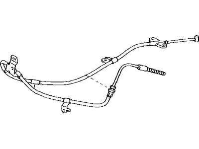
2007 Toyota Prius Front Cable
Part Number: 46410-47050$75.59 MSRP: $106.11You Save: $30.52 (29%)Ships in 1-3 Business DaysProduct Specifications- Other Name: Cable Assembly, Parking; Brake Cable; Cable Assembly, Parking Brake
- Part Name Code: 46410
- Item Weight: 2.00 Pounds
- Item Dimensions: 15.7 x 11.5 x 2.9 inches
- Condition: New
- Fitment Type: Direct Replacement
- SKU: 46410-47050
- Warranty: This genuine part is guaranteed by Toyota's factory warranty.
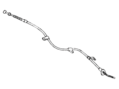
2007 Toyota Prius Cable
Part Number: 46430-47050$72.63 MSRP: $101.94You Save: $29.31 (29%)Ships in 1-3 Business DaysProduct Specifications- Other Name: Cable Assembly, Parking; Brake Cable; Cable Assembly, Parking Brake
- Part Name Code: 46430
- Item Weight: 2.30 Pounds
- Item Dimensions: 18.1 x 12.7 x 3.0 inches
- Condition: New
- Fitment Type: Direct Replacement
- SKU: 46430-47050
- Warranty: This genuine part is guaranteed by Toyota's factory warranty.
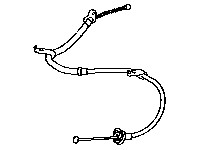
2007 Toyota Prius Cable
Part Number: 46420-47050$67.18 MSRP: $94.30You Save: $27.12 (29%)Ships in 1-3 Business DaysProduct Specifications- Other Name: Cable Assembly, Parking; Brake Cable; Cable Assembly, Parking Brake
- Part Name Code: 46420
- Item Weight: 2.70 Pounds
- Item Dimensions: 17.2 x 12.2 x 3.1 inches
- Condition: New
- Fitment Type: Direct Replacement
- SKU: 46420-47050
- Warranty: This genuine part is guaranteed by Toyota's factory warranty.
2007 Toyota Prius Parking Brake Cable
Looking for affordable OEM 2007 Toyota Prius Parking Brake Cable? Explore our comprehensive catalogue of genuine 2007 Toyota Prius Parking Brake Cable. All our parts are covered by the manufacturer's warranty. Plus, our straightforward return policy and speedy delivery service ensure an unparalleled shopping experience. We look forward to your visit!
2007 Toyota Prius Parking Brake Cable Parts Q&A
- Q: How to service and repair the parking brake cable on 2007 Toyota Prius?A: Service or repair of the parking brake cable starts by draining refrigerant from the refrigeration system then removing the suction hose sub-assembly along with cooler refrigerant liquid pipe E (to cooler unit) and heater water hoses A and B before you can remove the rear no. 2 floor board and rear deck floor box and rear no. 3 floor board. Disconnect the cable from the negative battery terminal, waiting at least 90 seconds to prevent Air Bag and seat belt pretensioner activation, then remove the instrument panel sub-assembly, no. 2 and no. 3 steering wheel cover lowers, steering pad assembly, steering wheel assembly, tilt lever bracket, steering column cover, turn signal switch assembly with spiral cable sub-assembly, front door scuff plates (LH and RH), cowl side trim boards (LH and RH), center instrument cluster finish panel assembly, radio receiver assembly, lower center instrument panel finish panel, glove compartment door lock cover and assembly, lower instrument panel finish panel, no. 1 instrument panel under cover sub-assembly, power steering ECU, shift lever assembly, rear no. 3 air duct, no. 3 heater to register duct, no. 1 heater to register duct, no. 2 heater to register duct, defroster nozzle assembly, ECM, hybrid vehicle control ECU, network gateway ECU, no. 1 instrument panel brace sub-assembly, air conditioning amplifier assembly, steering column assembly, instrument panel reinforcement assembly, front seat assembly (LH/RH), upper console panel sub-assembly, console box pocket, console box carpet, rear console box sub-assembly, front floor footrest, center Air Bag sensor assembly, yaw rate sensor (w/ VSC), no. 1 console box mounting bracket, and parking brake control pedal assembly. The procedure for removing the no. 1 parking brake cable assembly begins by unfixing the parking brake pedal claw followed by lock nut and adjusting nut removal from the parking brake pedal and subsequent clip release. The service repair order for rear brake replacement begins by unscrewing the rear wheel followed by the rear brake drum sub-assembly and proceeding to separate the parking brake shoe strut set LH. Subsequently, remove the front brake shoe and parking brake shoe strut set LH and rear brake automatic adjust lever LH along with rear brake shoe and rear brake parking brake shoe lever sub-assembly. Using a wrench to remove the heated oxygen sensor requires the disassembly of the two nuts alongside the front floor panel brace and front exhaust pipe assembly and parking brake cable heat insulator. To remove the no. 3 parking brake cable assembly begin by taking out its bolt and no. 3 parking brake cable from the backing plate before completing the removal of bolts and button to finally disconnect the cable from the parking brake equalizer. In the installation stage attach the no. 3 parking brake cable to the parking brake equalizer then bolt with button securement and notice a torque value of 5.4 Nm (55 kgf-cm, 48 inch lbs.) for Bolt A and 6.0 Nm (61 kgf-cm, 53 inch lbs.) for Bolt B after which mount it to the backing plate through a bolt at 8.0 Nm (82 kgf-cm, 71 inch lbs.). The installation starts by securing both nuts on the parking brake cable heat insulator with 5.4 Nm torque (55 kgf-cm or 48 inch lbs.), after which one should install the front exhaust pipe assembly and front floor panel brace while adding the heated oxygen sensor followed by high-temperature grease application. You should now attach the rear brake parking brake shoe lever sub-assembly followed by the rear brake shoe and rear brake shoe return spring then place the rear brake automatic adjust lever LH and parking brake shoe strut set LH before putting the front brake shoe in place and connecting the parking brake shoe strut set LH. For the rear brake assembly workers should check the drum setup and install the sub-assembly element then adjust the shoe clearance before placing the wheel and twisting the bracket to 103 Nm (1,050 kgf-cm, 76 ft. lbs.). Proceed with installing the no. 1 parking brake cable assembly by first inserting it through the pedal bracket and securing it with a new clip before passing it through the pedal guide and temporarily tightening the adjusting nut together with lock nut. Complete the installation when adjusting the parking brake pedal free play then bending the parking brake pedal claw fully. Complete the tightening of these parts before proceeding with free play adjustments for the parking brake pedal. Follow by fully bending the parking brake pedal claw as the final step. Install the parking brake control pedal assembly, no. 1 console box mounting bracket, yaw rate sensor (w/ VSC), center Air Bag sensor assembly, front floor footrest, front seat assembly (LH/RH), instrument panel reinforcement assembly, no. 1 instrument panel brace sub-assembly, fully tighten the air conditioning unit assembly, install the steering column assembly, lower instrument panel sub-assembly, shift lever assembly, power steering ECU, instrument panel sub-assembly, cooler refrigerant liquid pipe E (to cooler unit), suction hose sub-assembly, check for refrigerant leakage, position the spiral cable sub-assembly, install the steering column cover, tilt lever bracket, steering wheel assembly, and steering pad assembly, inspecting the steering pad assembly. Finally, connect the cable to the negative battery terminal, install the rear no. 3 floor board, rear deck floor box, rear no. 2 floor board, add engine coolant, charge refrigerant, check for engine coolant leakage, warm up the engine, inspect and adjust parking brake pedal travel, check the SRS warning light, perform torque sensor zero point calibration, and perform initialization, noting that certain systems need to be initialized after disconnecting and reconnecting the cable from the negative (-) battery terminal.


