×
ToyotaParts- Hello
- Login or Register
- Quick Links
- Live Chat
- Track Order
- Parts Availability
- RMA
- Help Center
- Contact Us
- Shop for
- Toyota Parts
- Scion Parts
My Garage
My Account
Cart
OEM 2007 Toyota Land Cruiser Air Injection Pump
SAI Pump- Select Vehicle by Model
- Select Vehicle by VIN
Select Vehicle by Model
orMake
Model
Year
Select Vehicle by VIN
For the most accurate results, select vehicle by your VIN (Vehicle Identification Number).
1 Air Injection Pump found


2007 Toyota Land Cruiser Pump Assembly, Air, Driver Side
Part Number: 17600-0F010$476.80 MSRP: $698.76You Save: $221.96 (32%)Ships in 1-3 Business DaysProduct Specifications- Other Name: Pump Assembly, Air W/Bra; Secondary Air Injection Pump
- Position: Driver Side
- Part Name Code: 17600C
- Item Weight: 2.30 Pounds
- Item Dimensions: 9.4 x 9.7 x 8.4 inches
- Condition: New
- Fitment Type: Direct Replacement
- SKU: 17600-0F010
- Warranty: This genuine part is guaranteed by Toyota's factory warranty.
2007 Toyota Land Cruiser Air Injection Pump
Looking for affordable OEM 2007 Toyota Land Cruiser Air Injection Pump? Explore our comprehensive catalogue of genuine 2007 Toyota Land Cruiser Air Injection Pump. All our parts are covered by the manufacturer's warranty. Plus, our straightforward return policy and speedy delivery service ensure an unparalleled shopping experience. We look forward to your visit!
2007 Toyota Land Cruiser Air Injection Pump Parts Q&A
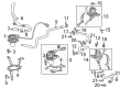
- Q: How to service and repair the Air Injection Pump on 2007 Toyota Land Cruiser?A: The repair of the Air Injection Pump starts by discharging fuel system pressure along with disconnecting the negative battery cable terminal but requiring at least 90 seconds of waiting time for safety. Removing the V-bank cover sub-assembly is necessary before draining the engine coolant and disconnecting both fuel body and fuel return hoses. The first step includes removing the intake air connector pipe and intake manifold assembly followed by removing the vacuum control valve set for the Air Injection System by taking out the 2 bolts securing the valve set from the intake manifold and disconnecting the 2 vacuum hoses. Uninstall the air pump assembly via disconnecting the No. 2 air hose and pressure sensor connector along with air switching valve connector then remove 4 bolts attaching the air pump. The No. 2 air switching valve removal involves disconnection of its 2 No. 3 air tubes from exhaust manifolds through 4 nut and 2 gasket removal followed by 4 bolt and 2 gasket removal with 2 No. 3 air tubes from 2 No. 2 air switching valves before removing 4 bolts and 2 gaskets and 2 No. 2 air switching valves from the rear water by-pass joint and both vacuum hoses from the No. 2 air switching valves. To remove the air injection control driver firstly disconnect the two connectors and then remove the two containing bolts. Begin with the installation of the air injection control driver by attaching 2 bolts which must receive a torque of 19.5 N.m (198 kgf.cm, 14 ft.lbf) while connecting its 2 connectors. You must first connect 2 vacuum hoses to the No. 2 air switching valve before adding new gaskets along with the 2 No. 2 air switching valves during their installation onto the rear water by-pass joint with appropriate torque setting. After that install 2 No. 3 air tubes by using new gaskets when connecting them between the No. 2 air switching valve and exhaust manifold. Attachment of the air pump assembly requires four bolts applying a torque of 16 N.m (163 kgf.cm, 12 ft.lbf) before reconnecting the pressure sensor connector and air switching valve connector and No. 2 air hose. Mount the vacuum control valve set to the intake manifold while tightening 2 bolts to 7.5 N.m (76 kgf.cm, 66 in.lbf). Then affix the two vacuum hoses. The repair process concludes with the installation of the intake manifold followed by the connection of fuel main and return hoses then addition of intakes air connector pipe together with V-bank cover sub-assembly. After reattaching the negative cable to the battery customers should perform system initializations before adding coolant while checking for leaks and fuel leakage.
Related 2007 Toyota Land Cruiser Parts
 2007 Toyota Land Cruiser Exhaust Manifold
 2007 Toyota Land Cruiser Muffler
 2007 Toyota Land Cruiser Canister Purge Valve
 2007 Toyota Land Cruiser Diverter Valve
 2007 Toyota Land Cruiser EGR Valve Gasket
 2007 Toyota Land Cruiser Exhaust Flange Gasket
 2007 Toyota Land Cruiser Exhaust Hanger
 2007 Toyota Land Cruiser Exhaust Heat Shield
 2007 Toyota Land Cruiser Exhaust Manifold Gasket
 2007 Toyota Land Cruiser Exhaust Pipe
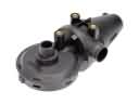 2007 Toyota Land Cruiser PCV Valve
 2007 Toyota Land Cruiser Vapor Canister