×
ToyotaParts- Hello
- Login or Register
- Quick Links
- Live Chat
- Track Order
- Parts Availability
- RMA
- Help Center
- Contact Us
- Shop for
- Toyota Parts
- Scion Parts
My Garage
My Account
Cart
OEM 2007 Toyota Camry Knock Sensor
Engine Knock Sensor- Select Vehicle by Model
- Select Vehicle by VIN
Select Vehicle by Model
orMake
Model
Year
Select Vehicle by VIN
For the most accurate results, select vehicle by your VIN (Vehicle Identification Number).
1 Knock Sensor found


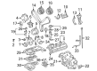
2007 Toyota Camry Knock Sensor
Part Number: 89615-06010$138.05 MSRP: $195.42You Save: $57.37 (30%)Ships in 1-3 Business DaysProduct Specifications- Other Name: Sensor, Knock Control; Ignition Knock (Detonation) Sensor
- Replaces: 89615-BZ030, 89615-20090, 89615-BZ040
- Part Name Code: 89615
- Item Weight: 0.40 Pounds
- Item Dimensions: 4.1 x 1.9 x 1.4 inches
- Condition: New
- Fitment Type: Direct Replacement
- SKU: 89615-06010
- Warranty: This genuine part is guaranteed by Toyota's factory warranty.
2007 Toyota Camry Knock Sensor
Looking for affordable OEM 2007 Toyota Camry Knock Sensor? Explore our comprehensive catalogue of genuine 2007 Toyota Camry Knock Sensor. All our parts are covered by the manufacturer's warranty. Plus, our straightforward return policy and speedy delivery service ensure an unparalleled shopping experience. We look forward to your visit!
2007 Toyota Camry Knock Sensor Parts Q&A
- Q: How to service the knock sensor on 2007 Toyota Camry?A: Before servicing the knock sensor you must discharge fuel system pressure along with removing the cable from the negative terminal. Start the knock sensor service by removing the No. 1 engine cover while draining coolant and unfastening both windshield wiper arm assemblies from left and right sides. The service begins with uninstalling both front fender to cowl side seals from both sides then continuing with removal of the cowl top ventilator louver sub-assembly followed by the windshield wiper motor and link and ending with the cowl top panel outer sub-assembly through bolt and nut removal. The technician should detach first the throttle body after removing the air cleaner cap sub-assembly and the air cleaner case sub-assembly. First disconnect the fuel tube before removing the fuel delivery pipe with injector followed by taking off the intake manifold by separating the union to check valve hose from the brake booster and the camshaft timing oil control valve connector and wire harness clamp and union to check valve hose from the vacuum hose clamp and terminating the process by removing the 5 bolts, 2 nuts, and the gasket from the intake manifold. The knock sensor requires the removal of its connector and nut before removing the sensor itself. The installation process starts with the knock sensor getting fastened with its nut into the right position before applying torque of 20 N.m (204 kgf.cm, 15 ft.lbf). After connecting the knock sensor connector you should place a new gasket within the intake manifold while using the 5 bolts with two nuts to secure it. Torque the assembly to a level of 30 N.m (306 kgf.cm, 22 ft.lbf). First position the vacuum hose clamp around the union to check valve hose then install the wire harness clamp and attach the camshaft timing oil control valve connector before uniting the brake booster with the union to check valve hose. The installation process requires the installer to fit the fuel delivery pipe followed by its injector and then add the throttle body and sequential air components - air cleaner case, air cleaner cap sub-assembly, air cleaner inlet assembly. Install the cable to the negative battery terminal then fill in engine coolant before conducting leak checks on engine coolant and fuel systems. The assembly work concludes with installation of the No. 1 engine cover sub-assembly using 4 bolts and 4 nuts (torque bolts to 5.0 N.m (51 kgf.cm, 44 in.lbf) and nuts to 85 N.m (867 kgf.cm, 44 ft.lbf)) while also adding the cowl top panel outer sub-assembly followed by windshield wiper motor and link attachment and cowl top ventilator louver sub-assembly before sealing both front fender to cowl side areas and installing windshield wiper arm and blade assemblies on both left and right sides.
Related 2007 Toyota Camry Parts
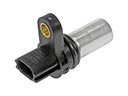 2007 Toyota Camry Camshaft Position Sensor
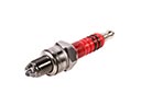 2007 Toyota Camry Spark Plug
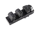 2007 Toyota Camry Power Window Switch
 2007 Toyota Camry Horn
 2007 Toyota Camry Oil Pressure Switch
 2007 Toyota Camry Crankshaft Position Sensor
 2007 Toyota Camry Door Jamb Switch
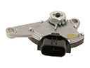 2007 Toyota Camry Neutral Safety Switch
 2007 Toyota Camry Ignition Lock Assembly
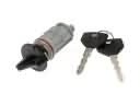 2007 Toyota Camry Ignition Lock Cylinder
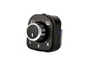 2007 Toyota Camry Mirror Switch
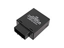 2007 Toyota Camry Turn Signal Flasher