×
ToyotaParts- Hello
- Login or Register
- Quick Links
- Live Chat
- Track Order
- Parts Availability
- RMA
- Help Center
- Contact Us
- Shop for
- Toyota Parts
- Scion Parts
My Garage
My Account
Cart
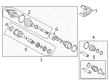
OEM 2007 Toyota Camry Axle Shaft
Car Axle Shaft- Select Vehicle by Model
- Select Vehicle by VIN
Select Vehicle by Model
orMake
Model
Year
Select Vehicle by VIN
For the most accurate results, select vehicle by your VIN (Vehicle Identification Number).
11 Axle Shafts found


2007 Toyota Camry Axle Assembly, Front Passenger Side
Part Number: 43410-06680$104.79 MSRP: $147.38You Save: $42.59 (29%)Product Specifications- Other Name: Shaft Assembly, Front Drive; CV Axle Assembly, Front Right; CV Axle Assembly; GSP Cv Axle; Axle Shaft
- Position: Front Passenger Side
- Replaces: 43410-06580
- Condition: New
- SKU: 43410-06680
- Warranty: This genuine part is guaranteed by Toyota's factory warranty.
2007 Toyota Camry Axle Assembly, Driver Side
Part Number: 43420-06B00$606.44 MSRP: $888.75You Save: $282.31 (32%)Product Specifications- Other Name: Shaft Assembly, Front Drive; CV Axle Assembly, Front Left; GSP Cv Axle; Axle Shaft; Shaft Assembly, Front Drive, Driver Side; CV Axle Assembly
- Manufacturer Note: KOREA SPEC
- Position: Driver Side
- Replaces: 43420-06860, 43420-0W210, 43420-06510
- Part Name Code: 43420
- Item Weight: 18.40 Pounds
- Item Dimensions: 29.5 x 7.7 x 6.9 inches
- Condition: New
- Fitment Type: Direct Replacement
- SKU: 43420-06B00
- Warranty: This genuine part is guaranteed by Toyota's factory warranty.

2007 Toyota Camry Axle Assembly, Front Passenger Side
Part Number: 43410-33311$420.85 MSRP: $616.76You Save: $195.91 (32%)Ships in 1-3 Business DaysProduct Specifications- Other Name: Shaft Assembly, Front Drive; CV Axle Assembly, Front Right; CV Axle Assembly; GSP Cv Axle; Axle Shaft
- Position: Front Passenger Side
- Replaces: 43410-33310
- Condition: New
- SKU: 43410-33311
- Warranty: This genuine part is guaranteed by Toyota's factory warranty.
2007 Toyota Camry Axle Assembly, Front Driver Side
Part Number: 43420-06750$313.84 MSRP: $474.62You Save: $160.78 (34%)Ships in 1-3 Business DaysProduct Specifications- Other Name: Shaft Assembly, Front Drive; CV Axle Assembly, Front Left; CV Axle Assembly; GSP Cv Axle; Axle Shaft
- Position: Front Driver Side
- Replaces: 43420-06610
- Item Weight: 14.80 Pounds
- Item Dimensions: 29.8 x 7.3 x 6.5 inches
- Condition: New
- SKU: 43420-06750
- Warranty: This genuine part is guaranteed by Toyota's factory warranty.
2007 Toyota Camry Shaft Assembly, Front Drive, Passenger Side
Part Number: 43410-06B80$368.59 MSRP: $566.74You Save: $198.15 (35%)Product Specifications- Other Name: Shaft Assembly, Front Drive; CV Axle Assembly; Axle Shaft
- Manufacturer Note: KOREA SPEC
- Position: Passenger Side
- Replaces: 43410-0W180, 43410-06A50, 43410-06560, 43410-06780
- Part Name Code: 43410
- Item Dimensions: 28.9 x 6.6 x 5.3 inches
- Condition: New
- Fitment Type: Direct Replacement
- SKU: 43410-06B80
- Warranty: This genuine part is guaranteed by Toyota's factory warranty.


2007 Toyota Camry Axle Assembly, Passenger Side
Part Number: 43410-06570$531.40 MSRP: $778.76You Save: $247.36 (32%)Ships in 1-3 Business DaysProduct Specifications- Other Name: Shaft Assembly, Front Drive; CV Axle Assembly, Front Right; GSP Cv Axle; Axle Shaft; Shaft Assembly, Front Drive, Passenger Side; CV Axle Assembly
- Position: Passenger Side
- Part Name Code: 43410
- Item Weight: 24.00 Pounds
- Item Dimensions: 42.8 x 5.7 x 5.5 inches
- Condition: New
- Fitment Type: Direct Replacement
- SKU: 43410-06570
- Warranty: This genuine part is guaranteed by Toyota's factory warranty.
2007 Toyota Camry Axle Assembly, Passenger Side
Part Number: 43410-33290$511.19 MSRP: $749.16You Save: $237.97 (32%)Ships in 1-3 Business DaysProduct Specifications- Other Name: Shaft Assembly, Front Drive; CV Axle Assembly, Front Right; GSP Cv Axle; Axle Shaft; Shaft Assembly, Front Drive, Passenger Side; CV Axle Assembly
- Manufacturer Note: (J)
- Position: Passenger Side
- Replaces: 43410-06670
- Part Name Code: 43410
- Item Weight: 24.00 Pounds
- Item Dimensions: 42.8 x 6.0 x 5.6 inches
- Condition: New
- Fitment Type: Direct Replacement
- SKU: 43410-33290
- Warranty: This genuine part is guaranteed by Toyota's factory warranty.
2007 Toyota Camry Axle Assembly, Driver Side
Part Number: 43420-33270$421.98 MSRP: $618.42You Save: $196.44 (32%)Ships in 1-3 Business DaysProduct Specifications- Other Name: Shaft Assembly, Front Drive; CV Axle Assembly, Front Left; GSP Cv Axle; Axle Shaft; Shaft Assembly, Front Drive, Driver Side; CV Axle Assembly
- Position: Driver Side
- Part Name Code: 43420
- Item Weight: 18.20 Pounds
- Item Dimensions: 30.9 x 6.4 x 6.2 inches
- Condition: New
- Fitment Type: Direct Replacement
- SKU: 43420-33270
- Warranty: This genuine part is guaranteed by Toyota's factory warranty.
2007 Toyota Camry Axle Assembly, Driver Side
Part Number: 43420-33250$421.98 MSRP: $618.42You Save: $196.44 (32%)Ships in 1-3 Business DaysProduct Specifications- Other Name: Shaft Assembly, Front Drive; CV Axle Assembly, Front Left; GSP Cv Axle; Axle Shaft; Shaft Assembly, Front Drive, Driver Side; CV Axle Assembly
- Manufacturer Note: (J)
- Position: Driver Side
- Replaces: 43420-06700
- Part Name Code: 43420
- Item Weight: 18.60 Pounds
- Item Dimensions: 31.6 x 5.5 x 5.3 inches
- Condition: New
- Fitment Type: Direct Replacement
- SKU: 43420-33250
- Warranty: This genuine part is guaranteed by Toyota's factory warranty.
2007 Toyota Camry Axle Assembly, Driver Side
Part Number: 43420-06600$437.62 MSRP: $641.33You Save: $203.71 (32%)Ships in 1-3 Business DaysProduct Specifications- Other Name: Shaft Assembly, Front Drive; CV Axle Assembly, Front Left; GSP Cv Axle; Axle Shaft; Shaft Assembly, Front Drive, Driver Side; CV Axle Assembly
- Position: Driver Side
- Part Name Code: 43420
- Item Weight: 18.40 Pounds
- Item Dimensions: 30.4 x 5.3 x 5.2 inches
- Condition: New
- Fitment Type: Direct Replacement
- SKU: 43420-06600
- Warranty: This genuine part is guaranteed by Toyota's factory warranty.
2007 Toyota Camry Axle Assembly, Driver Side
Part Number: 43420-33280$400.08 MSRP: $586.32You Save: $186.24 (32%)Ships in 1-3 Business DaysProduct Specifications- Other Name: Shaft Assembly, Front Drive; CV Axle Assembly, Front Left; GSP Cv Axle; Axle Shaft; Shaft Assembly, Front Drive, Driver Side; CV Axle Assembly
- Position: Driver Side
- Part Name Code: 43420
- Item Weight: 18.00 Pounds
- Item Dimensions: 30.1 x 5.3 x 5.3 inches
- Condition: New
- Fitment Type: Direct Replacement
- SKU: 43420-33280
- Warranty: This genuine part is guaranteed by Toyota's factory warranty.
2007 Toyota Camry Axle Shaft
Looking for affordable OEM 2007 Toyota Camry Axle Shaft? Explore our comprehensive catalogue of genuine 2007 Toyota Camry Axle Shaft. All our parts are covered by the manufacturer's warranty. Plus, our straightforward return policy and speedy delivery service ensure an unparalleled shopping experience. We look forward to your visit!
2007 Toyota Camry Axle Shaft Parts Q&A
- Q: How to service and repair the axle shaft on 2007 Toyota Camry?A: When servicing a TMC Made front drive shaft begin with automatic transaxle fluid drain or manual transaxle oil drain and proceed to remove the front wheel and front axle hub nut using Special Service Tool 09930-00010 together with a hammer to unstake the threads while protecting the drive shaft threads. The front stabilizer link assembly separation begins by removing the nut before inspecting the ball joint movement. Use a 6 mm hexagon wrench to stabilize the stud if the ball joint turns. Detach the speed sensor bolt and clip from the front component while checking that no debris sticks before using Special Service Tool: 09628-00011 to disconnect the tie rod end assembly without harming neighboring elements. You should start by marking the positions of the front suspension lower No. 1 arm and front axle assembly components. Then, use a plastic hammer to separate the front drive shaft assembly from the front axle assembly while protecting the drive shaft boot and speed sensor rotor from harm. Use Special Service Tool: 09520-01010, 09520-24010 (09520-32040) to take out the front drive shaft assembly LH first and then perform the same operation for the front drive shaft assembly RH after removing the bearing bracket hole snap ring along with its associated bolt. Apply weight pressure with caution to secure the front axle hub bearing through the installation of Special Service Tool: 09608-16042 (09608-02021, 09608-02041). To disassemble the front drive shaft begin by removing the front drive shaft LH hole snap ring after which the boot clamp on the No. 2 front axle inboard joint must be taken off for both 2GR-FE and 2AZ-FE models to separate the front axle inboard joint boot from the assembly. Remove the inboard joint assembly without punching marks yet note down positions and break the tripod joint loose from the outboard joint shaft using a brass bar and hammer which should stay away from the roller surface. The next step includes disassembly of front drive shaft dampers on both LH and RH sides while the outboard joint boot clamps and boot need to be removed last. The drive shaft dust covers need extraction with Special Service Tool: 09950-00020 combined with a press machine alongside Special Service Tool: 09527-10011 to extract the drive shaft bearing which requires careful handling during the entire procedure to avoid component damage. Check the front drive shaft assembly for suspension of the joint bearings while inspecting boot health.
Related 2007 Toyota Camry Parts
 2007 Toyota Camry Sway Bar Link
 2007 Toyota Camry Coil Springs
 2007 Toyota Camry Rear Crossmember
 2007 Toyota Camry Shock Absorber
 2007 Toyota Camry Bump Stop
 2007 Toyota Camry CV Joint
 2007 Toyota Camry Coil Spring Insulator
 2007 Toyota Camry Crossmember Bushing
 2007 Toyota Camry Lateral Link
 2007 Toyota Camry Suspension Strut Rod
 2007 Toyota Camry Sway Bar Bushing
 2007 Toyota Camry Sway Bar Kit