×
ToyotaParts- Hello
- Login or Register
- Quick Links
- Live Chat
- Track Order
- Parts Availability
- RMA
- Help Center
- Contact Us
- Shop for
- Toyota Parts
- Scion Parts
My Garage
My Account
Cart
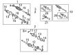
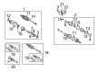
OEM 2006 Toyota Camry Axle Shaft
Car Axle Shaft- Select Vehicle by Model
- Select Vehicle by VIN
Select Vehicle by Model
orMake
Model
Year
Select Vehicle by VIN
For the most accurate results, select vehicle by your VIN (Vehicle Identification Number).
12 Axle Shafts found


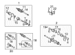
2006 Toyota Camry Axle Assembly, Passenger Side
Part Number: 43410-06450$464.88 MSRP: $681.29You Save: $216.41 (32%)Product Specifications- Other Name: Shaft Assembly, Front Drive; CV Axle Assembly, Front Right; GSP Cv Axle; Axle Shaft; Shaft Assembly, Front Drive, Passenger Side; CV Axle Assembly
- Position: Passenger Side
- Part Name Code: 43410
- Item Weight: 24.90 Pounds
- Item Dimensions: 43.7 x 5.5 x 5.6 inches
- Condition: New
- Fitment Type: Direct Replacement
- SKU: 43410-06450
- Warranty: This genuine part is guaranteed by Toyota's factory warranty.

2006 Toyota Camry Axle Assembly, Passenger Side
Part Number: 43410-0W081$510.10 MSRP: $747.56You Save: $237.46 (32%)Ships in 1-3 Business DaysProduct Specifications- Other Name: Shaft Assembly, Front Drive; CV Axle Assembly, Front Right; GSP Cv Axle; Axle Shaft; Shaft Assembly, Front Drive, Passenger Side; CV Axle Assembly
- Manufacturer Note: W(ABS)
- Position: Passenger Side
- Part Name Code: 43410
- Item Weight: 14.20 Pounds
- Item Dimensions: 30.4 x 7.8 x 6.9 inches
- Condition: New
- Fitment Type: Direct Replacement
- SKU: 43410-0W081
- Warranty: This genuine part is guaranteed by Toyota's factory warranty.
2006 Toyota Camry Axle Assembly, Passenger Side
Part Number: 43410-0W061$509.76 MSRP: $747.07You Save: $237.31 (32%)Ships in 1-3 Business DaysProduct Specifications- Other Name: Shaft Assembly, Front Drive; CV Axle Assembly, Front Right; GSP Cv Axle; Axle Shaft; Shaft Assembly, Front Drive, Passenger Side; CV Axle Assembly
- Manufacturer Note: W(ABS)
- Position: Passenger Side
- Part Name Code: 43410
- Item Weight: 14.20 Pounds
- Item Dimensions: 30.7 x 7.9 x 6.7 inches
- Condition: New
- Fitment Type: Direct Replacement
- SKU: 43410-0W061
- Warranty: This genuine part is guaranteed by Toyota's factory warranty.

2006 Toyota Camry Axle Assembly, Passenger Side
Part Number: 43410-0W110$509.26 MSRP: $746.33You Save: $237.07 (32%)Ships in 1-3 Business DaysProduct Specifications- Other Name: Shaft Assembly, Front Drive; CV Axle Assembly, Front Right; GSP Cv Axle; Axle Shaft; Shaft Assembly, Front Drive, Passenger Side; CV Axle Assembly
- Position: Passenger Side
- Part Name Code: 43410
- Item Weight: 25.90 Pounds
- Item Dimensions: 46.7 x 5.7 x 5.5 inches
- Condition: New
- Fitment Type: Direct Replacement
- SKU: 43410-0W110
- Warranty: This genuine part is guaranteed by Toyota's factory warranty.
2006 Toyota Camry Axle Assembly, Passenger Side
Part Number: 43410-0W140$488.52 MSRP: $715.92You Save: $227.40 (32%)Ships in 1-3 Business DaysProduct Specifications- Other Name: Shaft Assembly, Front Drive; CV Axle Assembly, Front Right; GSP Cv Axle; Axle Shaft; Shaft Assembly, Front Drive, Passenger Side; CV Axle Assembly
- Position: Passenger Side
- Part Name Code: 43410
- Item Weight: 24.70 Pounds
- Item Dimensions: 45.4 x 5.8 x 5.7 inches
- Condition: New
- Fitment Type: Direct Replacement
- SKU: 43410-0W140
- Warranty: This genuine part is guaranteed by Toyota's factory warranty.

2006 Toyota Camry Axle Assembly, Driver Side
Part Number: 43420-0W110$465.34 MSRP: $681.96You Save: $216.62 (32%)Ships in 1-3 Business DaysProduct Specifications- Other Name: Shaft Assembly, Front Drive; CV Axle Assembly, Front Left; GSP Cv Axle; Axle Shaft; Shaft Assembly, Front Drive, Driver Side; CV Axle Assembly
- Manufacturer Note: W(ABS)
- Position: Driver Side
- Replaces: 43420-0W061
- Part Name Code: 43420
- Item Weight: 14.10 Pounds
- Item Dimensions: 31.3 x 8.0 x 6.9 inches
- Condition: New
- Fitment Type: Direct Replacement
- SKU: 43420-0W110
- Warranty: This genuine part is guaranteed by Toyota's factory warranty.
2006 Toyota Camry Axle Assembly, Driver Side
Part Number: 43420-06490$465.00 MSRP: $681.46You Save: $216.46 (32%)Ships in 1-3 Business DaysProduct Specifications- Other Name: Shaft Assembly, Front Drive; CV Axle Assembly, Front Left; GSP Cv Axle; Axle Shaft; Shaft Assembly, Front Drive, Driver Side; CV Axle Assembly
- Manufacturer Note: W(ABS)
- Position: Driver Side
- Replaces: 43420-06221
- Part Name Code: 43420
- Item Weight: 7.30 Pounds
- Item Dimensions: 10.0 x 5.3 x 5.3 inches
- Condition: New
- Fitment Type: Direct Replacement
- SKU: 43420-06490
- Warranty: This genuine part is guaranteed by Toyota's factory warranty.

2006 Toyota Camry Axle Assembly, Driver Side
Part Number: 43420-0W170$397.00 MSRP: $581.80You Save: $184.80 (32%)Ships in 1-3 Business DaysProduct Specifications- Other Name: Shaft Assembly, Front Drive; CV Axle Assembly, Front Left; GSP Cv Axle; Axle Shaft; Shaft Assembly, Front Drive, Driver Side; CV Axle Assembly
- Position: Driver Side
- Replaces: 43420-0W150
- Part Name Code: 43420
- Item Weight: 20.90 Pounds
- Item Dimensions: 31.6 x 5.3 x 5.3 inches
- Condition: New
- Fitment Type: Direct Replacement
- SKU: 43420-0W170
- Warranty: This genuine part is guaranteed by Toyota's factory warranty.
2006 Toyota Camry Axle Assembly, Driver Side
Part Number: 43420-0W080$397.00 MSRP: $581.80You Save: $184.80 (32%)Ships in 1-3 Business DaysProduct Specifications- Other Name: Shaft Assembly, Front Drive; CV Axle Assembly, Front Left; GSP Cv Axle; Axle Shaft; Shaft Assembly, Front Drive, Driver Side; CV Axle Assembly
- Manufacturer Note: W(ABS)
- Position: Driver Side
- Part Name Code: 43420
- Item Weight: 15.20 Pounds
- Item Dimensions: 30.4 x 8.0 x 6.8 inches
- Condition: New
- Fitment Type: Direct Replacement
- SKU: 43420-0W080
- Warranty: This genuine part is guaranteed by Toyota's factory warranty.
2006 Toyota Camry Axle Assembly, Driver Side
Part Number: 43420-06450$459.44 MSRP: $673.30You Save: $213.86 (32%)Product Specifications- Other Name: Shaft Assembly, Front Drive; CV Axle Assembly, Front Left; GSP Cv Axle; Axle Shaft; Shaft Assembly, Front Drive, Driver Side; CV Axle Assembly
- Position: Driver Side
- Part Name Code: 43420
- Item Weight: 19.90 Pounds
- Item Dimensions: 29.8 x 5.3 x 5.2 inches
- Condition: New
- Fitment Type: Direct Replacement
- SKU: 43420-06450
- Warranty: This genuine part is guaranteed by Toyota's factory warranty.
2006 Toyota Camry Axle Assembly, Passenger Side
Part Number: 43410-06480$510.40 MSRP: $748.00You Save: $237.60 (32%)Product Specifications- Other Name: Shaft Assembly, Front Drive; CV Axle Assembly, Front Right; GSP Cv Axle; Axle Shaft; Shaft Assembly, Front Drive, Passenger Side; CV Axle Assembly
- Position: Passenger Side
- Part Name Code: 43410
- Item Weight: 25.20 Pounds
- Item Dimensions: 44.5 x 5.5 x 5.4 inches
- Condition: New
- Fitment Type: Direct Replacement
- SKU: 43410-06480
- Warranty: This genuine part is guaranteed by Toyota's factory warranty.
2006 Toyota Camry Axle Assembly, Passenger Side
Part Number: 43410-06221$510.40 MSRP: $748.00You Save: $237.60 (32%)Product Specifications- Other Name: Shaft Assembly, Front Drive; CV Axle Assembly, Front Right; GSP Cv Axle; Axle Shaft; Shaft Assembly, Front Drive, Passenger Side; CV Axle Assembly
- Manufacturer Note: W(ABS)
- Position: Passenger Side
- Part Name Code: 43410
- Item Weight: 15.30 Pounds
- Item Dimensions: 29.2 x 7.3 x 6.4 inches
- Condition: New
- Fitment Type: Direct Replacement
- SKU: 43410-06221
- Warranty: This genuine part is guaranteed by Toyota's factory warranty.
2006 Toyota Camry Axle Shaft
Looking for affordable OEM 2006 Toyota Camry Axle Shaft? Explore our comprehensive catalogue of genuine 2006 Toyota Camry Axle Shaft. All our parts are covered by the manufacturer's warranty. Plus, our straightforward return policy and speedy delivery service ensure an unparalleled shopping experience. We look forward to your visit!
2006 Toyota Camry Axle Shaft Parts Q&A
- Q: How to overhaul the axle shaft on 2006 Toyota Camry?A: The front drive shaft requires a drain of manual transaxle oil during overhaul by first removing the filler gasket followed by the drain gasket followed by new gasket installations at 49 Nm. First clean the automatic transaxle fluid from the drain plug while removing the gasket before replacing it with a new gasket and a drain plug at the same torque setting. Apply brakes to release the lock nut on the front axle hub while unstaking it with SST 09930-00010 and then removing its front wheel and front axle hub LH nut. When detaching the nut from the front stabilizer link assembly LH check if the ball joint rotates before clamping it with a hexagon wrench (6 mm). Detach the bolt and clip from the speed sensor front LH before separating the tie rod end sub-assembly LH with SST 09628-62011 to detach it from the steering knuckle. Separate the front suspension arm sub-assembly lower No. 1 LH by detaching its bolt and two nuts then disconnect the front axle assembly LH using a plastic hammer to prevent speed sensor rotor and drive shaft boot damage. Lift out the LH front drive shaft assembly while using SST 09520-01010, 09520-24010 (09520-32040) but maintain protection of the transaxle case oil seal and inboard joint boot and dust cover. Separating the front drive shaft assembly RH necessitates the removal of its bearing bracket hole snap ring followed by detaching the bolt to break its connection with the drive shaft bearing bracket. The fix points of the LH front axle hub sub-assembly require SST 09608-16042 (09608-02021, 09608-02041) to stop hub bearing damage. The inspection of front drive shaft assembly LH requires a check for radial play together with a damage inspection of the boots. Uninstall the inboard joint boot LH No.2 clamp followed by the inboard joint boot LH clamp to detach the inboard joint boot from its assembly. The front drive inboard joint assembly LH removal starts with marking both the outboard and inboard parts before detaching the assembly while using a snap ring expander tool to remove its shaft snap ring. To separate the tripod joint you should mark both the outboard joint shaft and tripod joint before using a brass bar with a hammer to detach it while avoiding contact with the roller. The manual transaxle vehicles must not have the front drive shaft damper LH installed along with the front drive shaft damper RH (except 1MZ-FE). Disassemble and wash away grease from the outboard joint shaft by removing its LH No.2 clamp and clamp then separating the outboard joint boot from the outboard joint shaft. Proceed to remove the front drive shaft dust cover LH No. 2 (w/o ABS) and the front drive shaft LH hole snap ring before extracting the front drive shaft dust cover LH and RH through the use of SST 09950-00020. Install a new bearing bracket hole snap ring and a new front drive shaft bearing by using SST 09527-30010 and 09527-10011 after removing the bearing with SST 09527-10011 and a snap ring expander. Install a new drive shaft dust cover with SST 09726-40010 and ensure complete installation while also performing the same installation for the front drive shaft dust cover RH according to engine type specifications. The installation of the front drive shaft LH hole snap ring and front wheel bearing dust deflector LH No.2 (w/o ABS) requires a specific distance measurement to be reached. The drive shaft spline needs vinyl tape after which technicians install the new outboard joint boot while using two clamps to pack it with grease per the specified amounts for different engines. Physically check the clearance of outboard joint boot LH No.2 by securing its clamp while adhering to specified maximum values. It is necessary to install the front drive shaft damper LH while maintaining proper distance and clamp position and measuring the resulting clearance. Use correct positioning for the front drive shaft damper RH (except 1MZ-FE) while measuring its clearance after installation. Tighten the tripod joint of the front drive inboard joint assembly LH by aligning matchmarks while using a hammer and brass bar. Afterward install a new shaft snap ring then pack outboard joint shaft and boot with grease. The mechanic must correctly position and measure the clearance of the front axle inboard joint boot along with the inboard joint boot LH No.2 clamp. Finally, install the front axle inboard joint boot LH clamp, checking the clearance, and inspect the front drive shaft for play and boot damage before installing the front drive shaft assembly LH and RH, ensuring proper alignment and torque specifications for all components, including the front axle assembly LH, front suspension arm sub-assembly lower No. 1 LH, tie rod end sub-assembly LH, speed sensor front LH, front stabilizer link assembly LH, and front axle hub LH nut, followed by reinstalling the front wheel and adding the necessary transaxle oils while inspecting fluid levels and adjusting the front wheel alignment.
Related 2006 Toyota Camry Parts
 2006 Toyota Camry Sway Bar Link
 2006 Toyota Camry Coil Springs
 2006 Toyota Camry Rear Crossmember
 2006 Toyota Camry Shock Absorber
 2006 Toyota Camry Bump Stop
 2006 Toyota Camry CV Joint
 2006 Toyota Camry Coil Spring Insulator
 2006 Toyota Camry Crossmember Bushing
 2006 Toyota Camry Lateral Link
 2006 Toyota Camry Suspension Strut Rod
 2006 Toyota Camry Sway Bar Bushing
 2006 Toyota Camry Sway Bar Kit