×
ToyotaParts- Hello
- Login or Register
- Quick Links
- Live Chat
- Track Order
- Parts Availability
- RMA
- Help Center
- Contact Us
- Shop for
- Toyota Parts
- Scion Parts
My Garage
My Account
Cart
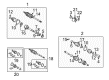
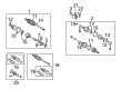
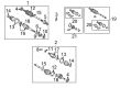
OEM 2005 Toyota Camry Axle Shaft
Car Axle Shaft- Select Vehicle by Model
- Select Vehicle by VIN
Select Vehicle by Model
orMake
Model
Year
Select Vehicle by VIN
For the most accurate results, select vehicle by your VIN (Vehicle Identification Number).
12 Axle Shafts found


2005 Toyota Camry Axle Assembly, Passenger Side
Part Number: 43410-06450$464.88 MSRP: $681.29You Save: $216.41 (32%)Product Specifications- Other Name: Shaft Assembly, Front Drive; CV Axle Assembly, Front Right; GSP Cv Axle; Axle Shaft; Shaft Assembly, Front Drive, Passenger Side; CV Axle Assembly
- Position: Passenger Side
- Part Name Code: 43410
- Item Weight: 24.90 Pounds
- Item Dimensions: 43.7 x 5.5 x 5.6 inches
- Condition: New
- Fitment Type: Direct Replacement
- SKU: 43410-06450
- Warranty: This genuine part is guaranteed by Toyota's factory warranty.

2005 Toyota Camry Axle Assembly, Passenger Side
Part Number: 43410-06480$510.40 MSRP: $748.00You Save: $237.60 (32%)Product Specifications- Other Name: Shaft Assembly, Front Drive; CV Axle Assembly, Front Right; GSP Cv Axle; Axle Shaft; Shaft Assembly, Front Drive, Passenger Side; CV Axle Assembly
- Position: Passenger Side
- Part Name Code: 43410
- Item Weight: 25.20 Pounds
- Item Dimensions: 44.5 x 5.5 x 5.4 inches
- Condition: New
- Fitment Type: Direct Replacement
- SKU: 43410-06480
- Warranty: This genuine part is guaranteed by Toyota's factory warranty.

2005 Toyota Camry Axle Assembly, Passenger Side
Part Number: 43410-0W081$510.10 MSRP: $747.56You Save: $237.46 (32%)Ships in 1-3 Business DaysProduct Specifications- Other Name: Shaft Assembly, Front Drive; CV Axle Assembly, Front Right; GSP Cv Axle; Axle Shaft; Shaft Assembly, Front Drive, Passenger Side; CV Axle Assembly
- Manufacturer Note: W(ABS)
- Position: Passenger Side
- Part Name Code: 43410
- Item Weight: 14.20 Pounds
- Item Dimensions: 30.4 x 7.8 x 6.9 inches
- Condition: New
- Fitment Type: Direct Replacement
- SKU: 43410-0W081
- Warranty: This genuine part is guaranteed by Toyota's factory warranty.
2005 Toyota Camry Axle Assembly, Passenger Side
Part Number: 43410-0W061$509.76 MSRP: $747.07You Save: $237.31 (32%)Ships in 1-3 Business DaysProduct Specifications- Other Name: Shaft Assembly, Front Drive; CV Axle Assembly, Front Right; GSP Cv Axle; Axle Shaft; Shaft Assembly, Front Drive, Passenger Side; CV Axle Assembly
- Manufacturer Note: W(ABS)
- Position: Passenger Side
- Part Name Code: 43410
- Item Weight: 14.20 Pounds
- Item Dimensions: 30.7 x 7.9 x 6.7 inches
- Condition: New
- Fitment Type: Direct Replacement
- SKU: 43410-0W061
- Warranty: This genuine part is guaranteed by Toyota's factory warranty.
2005 Toyota Camry Axle Assembly, Passenger Side
Part Number: 43410-0W110$509.26 MSRP: $746.33You Save: $237.07 (32%)Ships in 1-3 Business DaysProduct Specifications- Other Name: Shaft Assembly, Front Drive; CV Axle Assembly, Front Right; GSP Cv Axle; Axle Shaft; Shaft Assembly, Front Drive, Passenger Side; CV Axle Assembly
- Position: Passenger Side
- Part Name Code: 43410
- Item Weight: 25.90 Pounds
- Item Dimensions: 46.7 x 5.7 x 5.5 inches
- Condition: New
- Fitment Type: Direct Replacement
- SKU: 43410-0W110
- Warranty: This genuine part is guaranteed by Toyota's factory warranty.
2005 Toyota Camry Axle Assembly, Passenger Side
Part Number: 43410-0W140$488.52 MSRP: $715.92You Save: $227.40 (32%)Ships in 1-3 Business DaysProduct Specifications- Other Name: Shaft Assembly, Front Drive; CV Axle Assembly, Front Right; GSP Cv Axle; Axle Shaft; Shaft Assembly, Front Drive, Passenger Side; CV Axle Assembly
- Position: Passenger Side
- Part Name Code: 43410
- Item Weight: 24.70 Pounds
- Item Dimensions: 45.4 x 5.8 x 5.7 inches
- Condition: New
- Fitment Type: Direct Replacement
- SKU: 43410-0W140
- Warranty: This genuine part is guaranteed by Toyota's factory warranty.

2005 Toyota Camry Axle Assembly, Driver Side
Part Number: 43420-0W110$465.34 MSRP: $681.96You Save: $216.62 (32%)Ships in 1-3 Business DaysProduct Specifications- Other Name: Shaft Assembly, Front Drive; CV Axle Assembly, Front Left; GSP Cv Axle; Axle Shaft; Shaft Assembly, Front Drive, Driver Side; CV Axle Assembly
- Manufacturer Note: W(ABS)
- Position: Driver Side
- Replaces: 43420-0W061
- Part Name Code: 43420
- Item Weight: 14.10 Pounds
- Item Dimensions: 31.3 x 8.0 x 6.9 inches
- Condition: New
- Fitment Type: Direct Replacement
- SKU: 43420-0W110
- Warranty: This genuine part is guaranteed by Toyota's factory warranty.
2005 Toyota Camry Axle Assembly, Driver Side
Part Number: 43420-06490$465.00 MSRP: $681.46You Save: $216.46 (32%)Ships in 1-3 Business DaysProduct Specifications- Other Name: Shaft Assembly, Front Drive; CV Axle Assembly, Front Left; GSP Cv Axle; Axle Shaft; Shaft Assembly, Front Drive, Driver Side; CV Axle Assembly
- Manufacturer Note: W(ABS)
- Position: Driver Side
- Replaces: 43420-06221
- Part Name Code: 43420
- Item Weight: 7.30 Pounds
- Item Dimensions: 10.0 x 5.3 x 5.3 inches
- Condition: New
- Fitment Type: Direct Replacement
- SKU: 43420-06490
- Warranty: This genuine part is guaranteed by Toyota's factory warranty.

2005 Toyota Camry Axle Assembly, Driver Side
Part Number: 43420-0W170$397.00 MSRP: $581.80You Save: $184.80 (32%)Ships in 1-3 Business DaysProduct Specifications- Other Name: Shaft Assembly, Front Drive; CV Axle Assembly, Front Left; GSP Cv Axle; Axle Shaft; Shaft Assembly, Front Drive, Driver Side; CV Axle Assembly
- Position: Driver Side
- Replaces: 43420-0W150
- Part Name Code: 43420
- Item Weight: 20.90 Pounds
- Item Dimensions: 31.6 x 5.3 x 5.3 inches
- Condition: New
- Fitment Type: Direct Replacement
- SKU: 43420-0W170
- Warranty: This genuine part is guaranteed by Toyota's factory warranty.
2005 Toyota Camry Axle Assembly, Driver Side
Part Number: 43420-0W080$397.00 MSRP: $581.80You Save: $184.80 (32%)Ships in 1-3 Business DaysProduct Specifications- Other Name: Shaft Assembly, Front Drive; CV Axle Assembly, Front Left; GSP Cv Axle; Axle Shaft; Shaft Assembly, Front Drive, Driver Side; CV Axle Assembly
- Manufacturer Note: W(ABS)
- Position: Driver Side
- Part Name Code: 43420
- Item Weight: 15.20 Pounds
- Item Dimensions: 30.4 x 8.0 x 6.8 inches
- Condition: New
- Fitment Type: Direct Replacement
- SKU: 43420-0W080
- Warranty: This genuine part is guaranteed by Toyota's factory warranty.
2005 Toyota Camry Axle Assembly, Driver Side
Part Number: 43420-06450$459.44 MSRP: $673.30You Save: $213.86 (32%)Product Specifications- Other Name: Shaft Assembly, Front Drive; CV Axle Assembly, Front Left; GSP Cv Axle; Axle Shaft; Shaft Assembly, Front Drive, Driver Side; CV Axle Assembly
- Position: Driver Side
- Part Name Code: 43420
- Item Weight: 19.90 Pounds
- Item Dimensions: 29.8 x 5.3 x 5.2 inches
- Condition: New
- Fitment Type: Direct Replacement
- SKU: 43420-06450
- Warranty: This genuine part is guaranteed by Toyota's factory warranty.
2005 Toyota Camry Axle Assembly, Passenger Side
Part Number: 43410-06221$510.40 MSRP: $748.00You Save: $237.60 (32%)Product Specifications- Other Name: Shaft Assembly, Front Drive; CV Axle Assembly, Front Right; GSP Cv Axle; Axle Shaft; Shaft Assembly, Front Drive, Passenger Side; CV Axle Assembly
- Manufacturer Note: W(ABS)
- Position: Passenger Side
- Part Name Code: 43410
- Item Weight: 15.30 Pounds
- Item Dimensions: 29.2 x 7.3 x 6.4 inches
- Condition: New
- Fitment Type: Direct Replacement
- SKU: 43410-06221
- Warranty: This genuine part is guaranteed by Toyota's factory warranty.
2005 Toyota Camry Axle Shaft
Looking for affordable OEM 2005 Toyota Camry Axle Shaft? Explore our comprehensive catalogue of genuine 2005 Toyota Camry Axle Shaft. All our parts are covered by the manufacturer's warranty. Plus, our straightforward return policy and speedy delivery service ensure an unparalleled shopping experience. We look forward to your visit!
2005 Toyota Camry Axle Shaft Parts Q&A
- Q: How to overhaul the axle shaft on 2005 Toyota Camry?A: The first step in front drive shaft overhaul requires draining the manual transaxle oil through filler plug and gasket removal followed by drain plug removal. Reinstall the two new gaskets alongside the drain plug and filler plug while torquing them to 49 Nm (500 kgf-cm, 36 ft. lbs.). Draining the automatic transaxle fluid requires removing the drain plug and its gasket followed by draining the ATF before installing new gasket and drain plug and tightening it to 49 Nm (500 kgf-cm, 36 ft. lbs.). Use Special Service Tool: 09930-00010 together with a hammer to unstake the LH front axle hub nut because complete looseness prevents drive shaft screw damage. The lock axle hub LH nut must be removed when brakes are being applied. To separate the front stabilizer link assembly LH remove its nut though applying a hexagon wrench (6 mm) on the ball joint stud if it turns with the nut. To separate the speed sensor front LH from the steering knuckle you must first detach its bolt and clip without harming the sensor while subsequently removing the bolt to split it from the steering knuckle. You must start with the tie rod end sub-assembly LH since it requires you to eliminate the cotter pin and nut through the use of Special Service Tool: 09628-62011 for steering knuckle disconnection. You must separate the front suspension arm sub-assembly lower No. 1 LH by unscrewing its bolt and two nuts before detaching the front axle assembly LH with a plastic hammer until the front drive shaft assembly detaches from the axle hub but being mindful to not damage either the drive shaft boot or speed sensor rotor. Take out the LH front drive shaft assembly using Special Service Tools 09520-01010 and 09520-24010 (09520-32040) while protecting the transaxle case oil seal together with the inboard joint boot and drive shaft dust cover. The detachment of the drive shaft bearing bracket requires removal of both its bearing bracket hole snap ring and bolt for the front drive shaft assembly RH. To install the front axle hub sub-assembly LH use Special Service Tool: 09608-16042 (09608-02021, 09608-02041) while being careful to not harm the hub bearing. Determine if the LH front drive shaft assembly shows radial play at its outboard joint as well as proper sliding mechanics at the inboard joint along with checking for boot damage. You must separate the inboard joint boot from the inboard joint assembly by removing first the inboard joint boot LH No.2 clamp and then the inboard joint boot LH clamp. The procedure to remove the front drive inboard joint assembly LH begins with dressing the outboard joint shaft as well as the inboard joint assembly and removing their corresponding snap rings before marking the outboard joint shaft followed by the tripod joint removal. Extract both clamp and damper components from the front drive shaft damper LH and apply the same procedure to the front drive shaft damper RH (except 1MZ-FE). To access the outboard joint of the left-hand side you must first remove two clamps along with the boot and its grease. Use Special Service Tool: 09950-00020 and a press to uninstall the front drive shaft dust cover LH No. 2 (w/o ABS) and its front drive shaft LH hole snap ring. Finish by removing the front drive shaft dust cover LH and RH. Weld a new bearing bracket hole snap ring to the front driver shaft assembly RH as part of the driver front shaft assembly installation sequence. Install a new front drive shaft bearing after positioning the components correctly following the use of Special Service Tool: 09527-30010, 09527-10011 and a steel plate. Use Special Service Tool: 09726-40010 along with a press to install a new drive shaft dust cover while checking that the length between the center drive shaft tip and dust cover matches specifications. Follow the same procedure for the right-hand front drive shaft dust cover installation. A precision installation of the front drive shaft LH hole snap ring must be achieved before attaching the front wheel bearing dust deflector LH Number 2. Check that the distance from the front drive outboard joint shaft assembly tip (LH) to the deflector meets specified tolerances. A new outboard joint boot can be installed temporarily while grease is packed into the boot using the specified values for each engine model before the clamps are secured onto the boot. The installation process starts with front drive shaft damper LH and RH where proper clamp distances should be set and clamp tightening must reach specified clearances. Install the front drive inboard joint assembly LH while matching the marks and apply grease into the outboard joint shaft and boot. Measurably check the front axle inboard joint boot clearance after installing together with its clamps to validate proper specifications. The front drive shaft assembly LH and RH should be installed with proper alignment after checking for damage and play according to torque specifications. The last installation steps include attaching the front axle assembly LH alongside the front suspension arm sub-assembly lower No. 1 LH along with the tie rod end sub-assembly LH, speed sensor front LH, front stabilizer link assembly LH and front axle hub LH nut which requires staking before returning the front wheel and performing fluid checks on the transaxle system and wheel alignment tests and ABS speed sensor signal inspections.
Related 2005 Toyota Camry Parts
 2005 Toyota Camry Sway Bar Link
 2005 Toyota Camry Coil Springs
 2005 Toyota Camry Rear Crossmember
 2005 Toyota Camry Shock Absorber
 2005 Toyota Camry Bump Stop
 2005 Toyota Camry CV Joint
 2005 Toyota Camry Coil Spring Insulator
 2005 Toyota Camry Crossmember Bushing
 2005 Toyota Camry Lateral Link
 2005 Toyota Camry Suspension Strut Rod
 2005 Toyota Camry Sway Bar Bushing
 2005 Toyota Camry Sway Bar Kit