×
ToyotaParts- Hello
- Login or Register
- Quick Links
- Live Chat
- Track Order
- Parts Availability
- RMA
- Help Center
- Contact Us
- Shop for
- Toyota Parts
- Scion Parts
My Garage
My Account
Cart
OEM 2007 Toyota Avalon Wheel Hub
Wheel Axle Hub- Select Vehicle by Model
- Select Vehicle by VIN
Select Vehicle by Model
orMake
Model
Year
Select Vehicle by VIN
For the most accurate results, select vehicle by your VIN (Vehicle Identification Number).
3 Wheel Hubs found


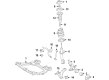
2007 Toyota Avalon Hub Assembly, Front
Part Number: 43502-0E030$130.65 MSRP: $184.95You Save: $54.30 (30%)Product Specifications- Other Name: Hub Sub-Assembly, Front Axle; Wheel Hub, Front; Front Hub & Bearing; Front Hub; Hub
- Position: Front
- Replaces: 43502-AA021, 43502-28100, 43502-08010, 43502-AA020
- Item Weight: 5.10 Pounds
- Item Dimensions: 6.6 x 6.9 x 4.6 inches
- Condition: New
- SKU: 43502-0E030
- Warranty: This genuine part is guaranteed by Toyota's factory warranty.


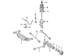
2007 Toyota Avalon Hub & Bearing Assembly, Rear Axle, Driver Side
Part Number: 42460-48011$478.62 MSRP: $701.43You Save: $222.81 (32%)Ships in 1-2 Business DaysProduct Specifications- Other Name: Hub&Bearing Assembly, Rear Axle; Wheel Hub Repair Kit; Bearing; Axle Bearing
- Position: Driver Side
- Replaces: 42460-06021, 42460-06020, 42460-48010, 42460-06030
- Part Name Code: 42450B
- Item Weight: 8.50 Pounds
- Item Dimensions: 7.0 x 6.8 x 7.3 inches
- Condition: New
- Fitment Type: Direct Replacement
- SKU: 42460-48011
- Warranty: This genuine part is guaranteed by Toyota's factory warranty.
2007 Toyota Avalon Hub Assembly, Passenger Side
Part Number: 42450-48011$515.62 MSRP: $755.65You Save: $240.03 (32%)Ships in 1 Business DayProduct Specifications- Other Name: Hub&Bearing Assembly, Rear Axle; Rear Right Wheel Bearing & Hub; Wheel Hub Repair Kit; Axle Bearing; Hub & Bearing Assembly, Rear Axle, Passenger Side; Wheel Bearing and Hub Assembly
- Position: Passenger Side
- Replaces: 42450-06030, 42450-48010, 42450-06020, 42450-06021, 42450-48020
- Part Name Code: 42450A
- Item Weight: 9.10 Pounds
- Item Dimensions: 6.8 x 6.9 x 7.7 inches
- Condition: New
- Fitment Type: Direct Replacement
- SKU: 42450-48011
- Warranty: This genuine part is guaranteed by Toyota's factory warranty.
2007 Toyota Avalon Wheel Hub
Looking for affordable OEM 2007 Toyota Avalon Wheel Hub? Explore our comprehensive catalogue of genuine 2007 Toyota Avalon Wheel Hub. All our parts are covered by the manufacturer's warranty. Plus, our straightforward return policy and speedy delivery service ensure an unparalleled shopping experience. We look forward to your visit!
2007 Toyota Avalon Wheel Hub Parts Q&A
- Q: How to service and repair the front Wheel Hub on 2007 Toyota Avalon?A: In order to maintain and repair the front wheel hub, unscrew the front wheel, brake caliper assembly and disc. Check the hub bearing regarding looseness and runout, and change when needed. Repeat these steps with the RH side, the components being taken apart. Reassemble with special tools, and make certain that all the work is adequately torqued and in place.
Related 2007 Toyota Avalon Parts
 2007 Toyota Avalon Wheel Bearing
 2007 Toyota Avalon Brake Caliper
 2007 Toyota Avalon Speed Sensor
 2007 Toyota Avalon Backing Plate
 2007 Toyota Avalon Brake Caliper Bracket
 2007 Toyota Avalon Brake Caliper Piston
 2007 Toyota Avalon Brake Pad Set
 2007 Toyota Avalon Hydraulic Hose
 2007 Toyota Avalon Parking Brake Shoe
 2007 Toyota Avalon Spindle Nut
 2007 Toyota Avalon Wheel Cylinder
 2007 Toyota Avalon Yaw Sensor