×
ToyotaParts- Hello
- Login or Register
- Quick Links
- Live Chat
- Track Order
- Parts Availability
- RMA
- Help Center
- Contact Us
- Shop for
- Toyota Parts
- Scion Parts
My Garage
My Account
Cart
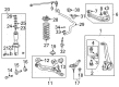
OEM 2006 Toyota Tundra Ball Joint
Control Arm Joint- Select Vehicle by Model
- Select Vehicle by VIN
Select Vehicle by Model
orMake
Model
Year
Select Vehicle by VIN
For the most accurate results, select vehicle by your VIN (Vehicle Identification Number).
3 Ball Joints found


2006 Toyota Tundra Upper Ball Joint, Front
Part Number: 43310-39016$49.94 MSRP: $69.51You Save: $19.57 (29%)Ships in 1-3 Business DaysProduct Specifications- Other Name: Joint Assembly, Front Upper Ball; Suspension Ball Joint, Front Upper; Upper Ball Joints; Front Upper Ball Joint Assembly for Driver & Passenger Side.
- Position: Front Upper
- Replaces: 43310-39085, 43310-39065
- Item Weight: 1.50 Pounds
- Item Dimensions: 5.5 x 3.2 x 2.5 inches
- Condition: New
- Fitment Type: Direct Replacement
- SKU: 43310-39016
- Warranty: This genuine part is guaranteed by Toyota's factory warranty.


2006 Toyota Tundra Lower Ball Joint, Front Driver Side
Part Number: 43340-39595$147.10 MSRP: $208.24You Save: $61.14 (30%)Product Specifications- Other Name: Joint Assembly, Lower Ball; Suspension Ball Joint, Front Left Lower; Joint Assembly, Lower Ball, Front Driver Side; Suspension Ball Joint; Ball Joint
- Position: Front Driver Side
- Replaces: 43340-39495, 43340-39575, 43340-39515
- Part Name Code: 43340A
- Item Weight: 3.30 Pounds
- Item Dimensions: 5.5 x 3.2 x 2.4 inches
- Condition: New
- Fitment Type: Direct Replacement
- SKU: 43340-39595
- Warranty: This genuine part is guaranteed by Toyota's factory warranty.


2006 Toyota Tundra Lower Ball Joint, Front Passenger Side
Part Number: 43330-39825$145.81 MSRP: $206.40You Save: $60.59 (30%)Product Specifications- Other Name: Joint Assembly, Lower Ball; Suspension Ball Joint, Front Right Lower; Joint Assembly, Lower Ball, Front Passenger Side; Suspension Ball Joint; Ball Joint
- Position: Front Passenger Side
- Replaces: 43330-39615, 43330-39805, 43330-39655
- Part Name Code: 43330K
- Item Weight: 5.10 Pounds
- Item Dimensions: 5.4 x 3.3 x 2.4 inches
- Condition: New
- Fitment Type: Direct Replacement
- SKU: 43330-39825
- Warranty: This genuine part is guaranteed by Toyota's factory warranty.
2006 Toyota Tundra Ball Joint
Looking for affordable OEM 2006 Toyota Tundra Ball Joint? Explore our comprehensive catalogue of genuine 2006 Toyota Tundra Ball Joint. All our parts are covered by the manufacturer's warranty. Plus, our straightforward return policy and speedy delivery service ensure an unparalleled shopping experience. We look forward to your visit!
2006 Toyota Tundra Ball Joint Parts Q&A
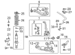
- Q: How to service and repair the front lower ball joint on 2006 Toyota Tundra?A: Service and repair operations for the front lower ball joint should start by removing the front wheel. The first step involves lightly loosening the 4 lower ball joint set bolts without taking them off before using Special Service Tool: 09610-20012 to disconnect the tie rod end by removing its cotter pin and nut. First unfasten the cotter pin and nut from the lower ball joint before using Special Service Tool: 09628-62011 to untether it from the lower suspension arm. Once free the lower ball joint and its dust cover protector can be taken out following removal of the 4 lower ball joint set bolts. During upper suspension arm and steering knuckle elevation, detach the lower ball joint before safely securing both components with a solid support. To check the ball joint rotation perform 5 back-and-forth movements with the stud before torqueing the nut to 0.1-2.5 Nm range (1-25 kgf-cm, 1-22 in.lbf) using a torque wrench which requires constant turning at 1 turn per 2-4 seconds during the 5th turn. Install the lower ball joint by first raising the steering knuckle and suspension arm before putting in the dust cover protector. First install the 4 lower ball joint bolts temporarily then apply the set nut to join the ball joint with the lower suspension arm while using a new cotter pin and tighten them to 159 Nm (J1200 kgf-cm, 117 ft-lbf). If the cotter pin holes are misaligned continue tightening the nut up to 60 degrees. Attach the tie rod end onto the lower ball joint through its nut and a fresh cotter pin before securely tightening both to 91 Nm at (930 kgf-cm and 67 ft.lbf) which follows the same misalignment adjustment procedures for the cotter pin. The front wheel can be installed after tightening the 4 lower ball joint set bolts to 65 Nm (662 kgf-cm, 48 ft-lbf). Front wheel alignment must be checked afterward.
Related 2006 Toyota Tundra Parts
 2006 Toyota Tundra Control Arm
 2006 Toyota Tundra Coil Springs
 2006 Toyota Tundra Sway Bar Link
 2006 Toyota Tundra Bump Stop
 2006 Toyota Tundra Sway Bar Kit
 2006 Toyota Tundra Alignment Bolt
 2006 Toyota Tundra Control Arm Bolt
 2006 Toyota Tundra Control Arm Bushing
 2006 Toyota Tundra Shock And Strut Mount
 2006 Toyota Tundra Strut Housing
 2006 Toyota Tundra Sway Bar Bushing
 2006 Toyota Tundra Wheel Seal