×
ToyotaParts- Hello
- Login or Register
- Quick Links
- Live Chat
- Track Order
- Parts Availability
- RMA
- Help Center
- Contact Us
- Shop for
- Toyota Parts
- Scion Parts
My Garage
My Account
Cart
OEM 2006 Toyota Avalon Axle Shaft
Car Axle Shaft- Select Vehicle by Model
- Select Vehicle by VIN
Select Vehicle by Model
orMake
Model
Year
Select Vehicle by VIN
For the most accurate results, select vehicle by your VIN (Vehicle Identification Number).
4 Axle Shafts found

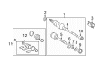
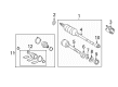
2006 Toyota Avalon Outer Joint Assembly, Driver Side
Part Number: 43470-09N20$248.61 MSRP: $354.96You Save: $106.35 (30%)Ships in 1-3 Business DaysProduct Specifications- Other Name: Shaft Assembly Set, Outboard; CV Joint
- Position: Driver Side
- Condition: New
- SKU: 43470-09N20
- Warranty: This genuine part is guaranteed by Toyota's factory warranty.
2006 Toyota Avalon Outer Joint Assembly, Passenger Side
Part Number: 43460-09P20$251.16 MSRP: $358.60You Save: $107.44 (30%)Ships in 1-3 Business DaysProduct Specifications- Other Name: Shaft Assembly Set, Outboard; CV Joint
- Position: Passenger Side
- Condition: New
- SKU: 43460-09P20
- Warranty: This genuine part is guaranteed by Toyota's factory warranty.

2006 Toyota Avalon Axle Assembly, Driver Side
Part Number: 43420-07070$436.46 MSRP: $639.64You Save: $203.18 (32%)Ships in 1-3 Business DaysProduct Specifications- Other Name: Shaft Assembly, Front Drive; CV Axle Assembly, Front Left; GSP Cv Axle; Axle Shaft; Shaft Assembly, Front Drive, Driver Side; CV Axle Assembly
- Position: Driver Side
- Part Name Code: 43420
- Item Weight: 18.40 Pounds
- Item Dimensions: 31.0 x 5.3 x 5.2 inches
- Condition: New
- Fitment Type: Direct Replacement
- SKU: 43420-07070
- Warranty: This genuine part is guaranteed by Toyota's factory warranty.

2006 Toyota Avalon Axle Assembly, Passenger Side
Part Number: 43410-07071$545.29 MSRP: $799.13You Save: $253.84 (32%)Product Specifications- Other Name: Shaft Assembly, Front Drive; CV Axle Assembly, Front Right; GSP Cv Axle; Axle Shaft; Shaft Assembly, Front Drive, Passenger Side; CV Axle Assembly
- Position: Passenger Side
- Replaces: 43410-07070
- Part Name Code: 43410
- Item Weight: 7.70 Pounds
- Item Dimensions: 28.9 x 7.5 x 6.4 inches
- Condition: New
- Fitment Type: Direct Replacement
- SKU: 43410-07071
- Warranty: This genuine part is guaranteed by Toyota's factory warranty.
2006 Toyota Avalon Axle Shaft
Looking for affordable OEM 2006 Toyota Avalon Axle Shaft? Explore our comprehensive catalogue of genuine 2006 Toyota Avalon Axle Shaft. All our parts are covered by the manufacturer's warranty. Plus, our straightforward return policy and speedy delivery service ensure an unparalleled shopping experience. We look forward to your visit!
2006 Toyota Avalon Axle Shaft Parts Q&A
- Q: How to service and repair the axle shaft components on 2006 Toyota Avalon?A: Service and repair operations on front drive shaft components start with unbolting the engine under cover LH and draining automatic transaxle fluid through drain plug removal followed by new gasket installation and proper torque of 49 Nm (500 kgf-cm, 36 ft. lbs.) on the drain plug. Use SST 09930-00010 to eliminate the front wheel and its front axle hub LH nut while checking that the staked part is entirely loose to protect the drive shaft screw. To break apart the front stabilizer link assembly LH you must first remove its nut which may cause the ball joint to turn so use a 6 mm hexagon wrench to keep the stud stationary. Detach the speed sensor front LH by removing its bolt with the clip attached followed by the bolt on the steering knuckle using caution to shield the sensor from foreign particles. Lift off the tie rod end sub-assembly LH through nut and cotter pin removal while using SST 09628-62011 to disconnect it from the steering knuckle unit without harming the ball joint dust cover. The next step for front suspension requires removal of bolt and two nuts from the front suspension arm sub-assembly lower No.1 LH before finally breaking the front axle assembly LH by marking the front drive shaft assembly LH and axle hub and using a plastic hammer to prevent damage to the drive shaft boot and speed sensor rotor. Remove the front drive shaft assembly LH using SST 09520-01010, 09520-24010 (09520-32040) by carefully detaching the assembly while protecting the dust cover and boot along with the oil seal. Finally separate the front drive shaft assembly RH after removing its bearing bracket hole snap ring together with its bolt. SST 09608-16042 (09608-02021, 09608-02041) should be used to fix the front axle hub sub-assembly LH while protecting the hub bearing. Excessive play and boot damage should be checked on the front drive shaft assembly LH and then the front drive inner shaft outer LH shaft snap ring and inboard joint boot clamps must be removed using pliers. The operation to withdraw the LH front drive inboard joint assembly begins by marking the outboard joint assembly and outboard joint shaft followed by detaching the tripod joint from the outboard joint shaft through strikes from a brass bar and hammer stroke. This step cannot include roller tapping. First remove the front drive shaft damper LH while also removing its clamps from the outboard joint boot followed by boot and joint grease removal from the outboard joint. Use SST 09950-00020 and 09527-10011 to extract the front drive shaft dust cover LH, RH with the drive shaft bearing from the system without letting the inboard joint assembly hit the floor. The installer should install a new bearing bracket hole snap ring before using SST 09527-30010, 09527-10011 to add a new front drive shaft bearing followed by installing a new drive shaft dust cover with SST 09726-40010 until complete installation. The spline of the drive shaft requires vinyl tape wrapping before installing the outboard joint boot while grease filling (120 to 140 g) between the outboard joint shaft and boot. First, install the front axle outboard joint boot clamp using SST 09240-00020 and confirm the correct space between components before you put on the front drive shaft damper LH and check its placement. The front drive inboard joint assembly LH requires installation while following the snap ring expander process for the new shaft snap ring along with outboard joint shaft and boot grease application of 190 to 210 g. After installing the inboard joint boot along with its clamps, check the front drive shaft for both boot deterioration and abnormal movements. Plug a new hole snap ring to the inboard joint shaft assembly, apply ATF along its splined surface and position the snap ring correctly before installing the drive shaft assembly LH. Repeat the process for the RH assembly of the front drive shaft and torques the new bolt to 32 Nm (330 kgf-cm, 24 ft. lbs.) while avoiding boot or oil seal damage. When performing installation, first align the matchmarks then attach the front axle assembly LH followed by the front suspension arm sub-assembly lower No.1 LH which requires a torque of 75 Nm (765 kgf-cm, 55 ft. lbs.) before installing the tie rod end sub-assembly LH with 49 Nm (500 kgf-cm, 36 ft. lbs.) along with a new cotter pin. Hook up the speed sensor front LH by applying 8.0 Nm (82 kgf-cm, 71 inch lbs.) torque and connect the flexible hose to the shock absorber via 19 Nm (192 kgf-cm, 14 ft. lbs.) torque while controlling sensor contact with foreign matter. Finish the repair by torquing the front stabilizer link assembly LH to 74 Nm (755 kgf-cm, 55 ft. lbs.), installing front axle hub LH nut at 294 Nm (3,000 kgf-cm, 217 ft. lbs.), and tightening front wheel to 103 Nm (1,050 kgf-cm, 76 ft. lbs.). Additionally, add and inspect automatic transaxle fluid, check front wheel alignment and install engine under cover LH before testing ABS speed sensor signal.
Related 2006 Toyota Avalon Parts
 2006 Toyota Avalon Control Arm
 2006 Toyota Avalon Bump Stop
 2006 Toyota Avalon CV Boot
 2006 Toyota Avalon CV Joint
 2006 Toyota Avalon Coil Spring Insulator
 2006 Toyota Avalon Coil Springs
 2006 Toyota Avalon Lateral Link
 2006 Toyota Avalon Shock And Strut Mount
 2006 Toyota Avalon Strut Housing
 2006 Toyota Avalon Sway Bar Bracket
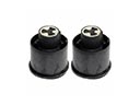 2006 Toyota Avalon Trailing Arm Bushing
 2006 Toyota Avalon Transfer Case Output Shaft Snap Ring