×
ToyotaParts- Hello
- Login or Register
- Quick Links
- Live Chat
- Track Order
- Parts Availability
- RMA
- Help Center
- Contact Us
- Shop for
- Toyota Parts
- Scion Parts
My Garage
My Account
Cart
OEM 2006 Toyota Avalon Coil Springs
Strut Spring- Select Vehicle by Model
- Select Vehicle by VIN
Select Vehicle by Model
orMake
Model
Year
Select Vehicle by VIN
For the most accurate results, select vehicle by your VIN (Vehicle Identification Number).
5 Coil Springs found

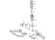
2006 Toyota Avalon Coil Spring, Front
Part Number: 48131-07093$97.75 MSRP: $137.21You Save: $39.46 (29%)Ships in 1-3 Business DaysProduct Specifications- Other Name: Spring, Coil, Front; Coil Spring, Front; Coil Springs; Spring; Spring, Front Coil, Passenger Side; Spring, Front Coil, Driver Side
- Manufacturer Note: SPORTS PACKAGE
- Position: Front
- Replaces: 48131-07092
- Item Weight: 7.10 Pounds
- Item Dimensions: 15.6 x 7.1 x 5.9 inches
- Condition: New
- Fitment Type: Direct Replacement
- SKU: 48131-07093
- Warranty: This genuine part is guaranteed by Toyota's factory warranty.

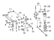
2006 Toyota Avalon Coil Spring, Rear
Part Number: 48231-07071$96.45 MSRP: $135.38You Save: $38.93 (29%)Ships in 1-3 Business DaysProduct Specifications- Other Name: Spring, Coil, Rear; Coil Spring, Rear; Coil Springs; Spring; Spring, Coil, Rear Passenger Side; Spring, Coil, Rear Driver Side
- Manufacturer Note: SPORTS PACKAGE
- Position: Rear
- Replaces: 48231-07070
- Item Weight: 4.30 Pounds
- Item Dimensions: 17.5 x 11.0 x 5.8 inches
- Condition: New
- Fitment Type: Direct Replacement
- SKU: 48231-07071
- Warranty: This genuine part is guaranteed by Toyota's factory warranty.
2006 Toyota Avalon Coil Spring, Rear
Part Number: 48231-07061$95.85 MSRP: $134.55You Save: $38.70 (29%)Ships in 1-3 Business DaysProduct Specifications- Other Name: Spring, Coil, Rear; Coil Spring, Rear, Rear Left, Rear Right; Coil Springs; Spring; Spring, Coil, Rear Passenger Side; Spring, Coil, Rear Driver Side
- Position: Rear
- Replaces: 48231-07060
- Item Weight: 4.40 Pounds
- Item Dimensions: 16.8 x 11.0 x 5.8 inches
- Condition: New
- Fitment Type: Direct Replacement
- SKU: 48231-07061
- Warranty: This genuine part is guaranteed by Toyota's factory warranty.
2006 Toyota Avalon Coil Spring, Front
Part Number: 48131-07082$95.03 MSRP: $133.38You Save: $38.35 (29%)Ships in 1-3 Business DaysProduct Specifications- Other Name: Spring, Coil, Front; Coil Spring, Front, Front Left, Front Right; Coil Springs; Spring; Spring, Front Coil, Passenger Side; Spring, Front Coil, Driver Side
- Position: Front
- Item Weight: 6.10 Pounds
- Item Dimensions: 15.9 x 7.1 x 5.8 inches
- Condition: New
- Fitment Type: Direct Replacement
- SKU: 48131-07082
- Warranty: This genuine part is guaranteed by Toyota's factory warranty.
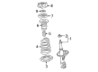
2006 Toyota Avalon Spring, Front
Part Number: 48131-07090$104.47 MSRP: $146.65You Save: $42.18 (29%)Ships in 1-3 Business DaysProduct Specifications- Other Name: Spring, Coil, Front; Coil Spring, Front; Coil Spring Kit Front; Coil Spring Set; Coil Springs; Spring, Front Coil, Passenger Side; Spring, Front Coil, Driver Side
- Manufacturer Note: SPORTS PACKAGE
- Position: Front
- Item Weight: 7.00 Pounds
- Item Dimensions: 15.5 x 6.9 x 5.8 inches
- Condition: New
- Fitment Type: Direct Replacement
- SKU: 48131-07090
- Warranty: This genuine part is guaranteed by Toyota's factory warranty.
2006 Toyota Avalon Coil Springs
Looking for affordable OEM 2006 Toyota Avalon Coil Springs? Explore our comprehensive catalogue of genuine 2006 Toyota Avalon Coil Springs. All our parts are covered by the manufacturer's warranty. Plus, our straightforward return policy and speedy delivery service ensure an unparalleled shopping experience. We look forward to your visit!
2006 Toyota Avalon Coil Springs Parts Q&A
- Q: How to overhaul the front shock absorber with coil springs on 2006 Toyota Avalon?A: Start the front shock absorber with coil spring overhaul by removing the front wheel alongside the front stabilizer link assembly LH separation by unthreading its nut and discharging its connection to shock absorber assembly front LH while applying hexagon (6 mm) wrench to hold the stud for ball joint turning. Loosening the lock nut on the front shock absorber is next in the procedure yet complete disassembly does not require unlocking the nut. To start this procedure disconnect the front flexible hose No.1 and speed sensor front LH wire harness by removing the bolt. Afterwards remove the 2 nuts on the lower side and the 3 nuts on the upper side of the front shock absorber with coil spring and keep all bolts inside. Lower side bolts must be removed with caution since dropping the collar can occur when a front suspension upper brace center exists. The front shock absorber with coil spring needs a vise that clamps a double nutted bolt from its bottom attachment bracket. You should use Special Service Tool: 09727-30021 (09727-00010, 09727-00021) to compress the front coil spring LH while avoiding impact wrench use for tool integrity and then detach the front suspension support sub-assembly LH, front suspension support bearing LH, front coil spring seat upper LH, front coil spring insulator upper LH, front coil spring LH, front spring bumper LH, and front coil spring insulator lower LH from the shock absorber assembly front LH. Inspect the shock absorber assembly via the shock absorber rod operation at least 4 times to identify any unusual resistance and noise production ensuring a replacement of defective units. Begin with the placement of front coil spring insulator lower LH onto shock absorber assembly front LH then add front spring bumper LH to the piston rod. Repeat the use of the Special Service Tool to compress the front coil spring LH before installing the front coil spring LH into its position where the lower end should rest inside the front coil spring lower LH gap. Proceed by first installing the front coil spring insulator upper LH then add the front coil spring seat upper LH with its mark oriented to the exterior while following with a fresh front suspension support bearing LH and finishing with the front suspension support sub-assembly LH facing the outer direction. Use the Special Service Tool to adjust the spring tension before pulling the tool from the front coil spring slowly. The assembly of the front shock absorber with coil spring requires the installation of upper side nuts before applying torque to 85 Nm (867 kgf-cm, 63 ft. lbs.) before proceeding to lower side bolts and nuts torqued to 210 Nm (2,140 kgf-cm, 155 ft. lbs.) while keeping bolts stationary. Fasten the lock nut completely to 49 Nm (500 kgf-cm, 36 ft. lbs.) before attaching the front flexible hose No.1 and speed sensor front LH through the bolt secured by 19 Nm (192 kgf-cm, 14 ft. lbs.). Reinstall the front wheel while torquing it to 103 Nm (1,050 kgf-cm, 76 ft. lbs.). Next check and adjust the front wheel alignment before torquing the front stabilizer link assembly LH with its nut to 74 Nm (755 kgf-cm, 55 ft. lbs.).
Related 2006 Toyota Avalon Parts
 2006 Toyota Avalon Ball Joint
 2006 Toyota Avalon Coil Spring Insulator
 2006 Toyota Avalon Control Arm Bushing
 2006 Toyota Avalon Crossmember Bushing
 2006 Toyota Avalon Front Cross-Member
 2006 Toyota Avalon Rear Crossmember
 2006 Toyota Avalon Shock Absorber
 2006 Toyota Avalon Shock and Strut Boot
 2006 Toyota Avalon Steering Knuckle
 2006 Toyota Avalon Strut Housing
 2006 Toyota Avalon Sway Bar Bushing
 2006 Toyota Avalon Sway Bar Kit