×
ToyotaParts- Hello
- Login or Register
- Quick Links
- Live Chat
- Track Order
- Parts Availability
- RMA
- Help Center
- Contact Us
- Shop for
- Toyota Parts
- Scion Parts
My Garage
My Account
Cart
OEM 2006 Toyota Avalon Control Arm
Suspension Arm- Select Vehicle by Model
- Select Vehicle by VIN
Select Vehicle by Model
orMake
Model
Year
Select Vehicle by VIN
For the most accurate results, select vehicle by your VIN (Vehicle Identification Number).
3 Control Arms found


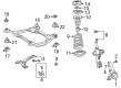
2006 Toyota Avalon Control Arm, Lower Driver Side
Part Number: 48069-06100$169.42 MSRP: $239.84You Save: $70.42 (30%)Ships in 1 Business DayProduct Specifications- Other Name: Arm Sub-Assembly, Suspension; Suspension Control Arm, Front Left; Control Arm Assembly; Lower Control Arm; Arm Sub-Assembly, Front Suspension, Lower Driver Side; Suspension Control Arm
- Position: Lower Driver Side
- Replaces: 48069-58010, 48069-28120
- Part Name Code: 48069
- Item Weight: 10.60 Pounds
- Item Dimensions: 2.9 x 2.9 x 2.8 inches
- Condition: New
- Fitment Type: Direct Replacement
- SKU: 48069-06100
- Warranty: This genuine part is guaranteed by Toyota's factory warranty.

2006 Toyota Avalon Control Arm, Passenger Side
Part Number: 48068-06100$161.79 MSRP: $229.03You Save: $67.24 (30%)Ships in 1 Business DayProduct Specifications- Other Name: Arm Sub-Assembly, Suspension; Suspension Control Arm, Front Right; Control Arm Assembly; Lower Control Arm; Arm Sub-Assembly, Front Suspension, Lower Passenger Side; Suspension Control Arm
- Position: Passenger Side
- Replaces: 48068-28120, 48068-58010
- Part Name Code: 48068
- Item Weight: 7.80 Pounds
- Item Dimensions: 18.2 x 2.8 x 15.4 inches
- Condition: New
- Fitment Type: Direct Replacement
- SKU: 48068-06100
- Warranty: This genuine part is guaranteed by Toyota's factory warranty.

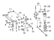
2006 Toyota Avalon Control Arm, Rear Passenger Side
Part Number: 48730-33150$121.95 MSRP: $172.64You Save: $50.69 (30%)Ships in 1-3 Business DaysProduct Specifications- Other Name: Arm Assembly, Rear Suspension; Suspension Control Arm; Rear Lateral Arm; Arm
- Position: Rear Passenger Side
- Replaces: 48730-07030, 48730-07050
- Item Weight: 1.80 Pounds
- Item Dimensions: 9.2 x 1.9 x 1.9 inches
- Condition: New
- SKU: 48730-33150
- Warranty: This genuine part is guaranteed by Toyota's factory warranty.
2006 Toyota Avalon Control Arm
Looking for affordable OEM 2006 Toyota Avalon Control Arm? Explore our comprehensive catalogue of genuine 2006 Toyota Avalon Control Arm. All our parts are covered by the manufacturer's warranty. Plus, our straightforward return policy and speedy delivery service ensure an unparalleled shopping experience. We look forward to your visit!
2006 Toyota Avalon Control Arm Parts Q&A
- Q: How to replace the Rear Control Arm No.1 on 2006 Toyota Avalon?A: The process for Rear Suspension Arm No.1 replacement starts with dismantling the rear wheel followed by removing the exhaust pipe assembly center, stabilizer bar rear and strut rod assembly rear from the vehicle. The height control sensor sub-assembly rear RH requires nut removal as it exists only on the right-hand side of the vehicle. Detach the rear suspension arm assembly No.2 LH by taking out its bolt and nut yet preventing nut rotation. Use the identical method to detach suspension components from the RH side. Separate the rear suspension arm assembly No.1 LH by removing the bolt and nut and arm from the rear axle carrier while preventing the nut rotation and repeat the same procedure for the RH side. Start by using a jack for supporting the rear suspension member before removing 4 nuts and 2 bolts and 4 retainers then releasing the member. Install the rear suspension arm No.1 LH with its bolt while securing the bracket in an angle that points towards the front side with the paint mark facing the rear direction. Then fully tighten the bolt to 100 Nm (1,020 kgf-cm, 74 ft. lbs.). The arm should be placed in its exact position before torqueing the bolt to 100 Nm (1,020 kgf-cm, 74 ft. lbs.). Install the rear suspension member by using four nuts, two bolts, and four retainers and torque them to these specifications: A, B - 55 Nm (561 kgf-cm, 41 ft. lbs.) and C: 38 Nm (387 kgf-cm, 28 ft. lbs.). Install the bolt through the front end of the temporary rear suspension arm assembly No.1 LH into the rear axle carrier and follow up with the same process for the right-hand side. Drill the same procedures to temporarily tighten the rear suspension arm assembly No.2 LH and RH. After temporarily tightening the strut rod assembly rear and by using a wooden block on the rear axle carrier to stabilize the suspension properly, check that the installed bolt of the suspension arm assembly No.1 points straight horizontally with the center of the rear axle hub. While tightening the rear suspension arm assembly No.1 LH to 100 Nm (1,020 kgf-cm, 74 ft. lbs.) the technician should also secure the nut. Fasten the rear suspension arm assembly No.2 LH and RH until they reach the same torque specification and maintain consistent torque while fixing the nut for installation. Follow this order for installation: first tightly secure the strut rod assembly rear but afterward add the stabilizer bar rear and lastly attach and torque to 5.4 Nm (55 kgf-cm, 48 inch lbs.) the height control sensor sub-assembly rear RH. After reinstalling the exhaust pipe assembly center and rear wheel you should tighten the wheel to 103 Nm (1,050 kgf-cm, 76 ft. lbs.) before examining the rear wheel alignment together with making discharge headlights adjustment when present.
Related 2006 Toyota Avalon Parts
 2006 Toyota Avalon Bump Stop
 2006 Toyota Avalon Coil Spring Insulator
 2006 Toyota Avalon Coil Springs
 2006 Toyota Avalon Control Arm Bushing
 2006 Toyota Avalon Front Cross-Member
 2006 Toyota Avalon Lateral Link
 2006 Toyota Avalon Shock And Strut Mount
 2006 Toyota Avalon Strut Housing
 2006 Toyota Avalon Suspension Strut Rod
 2006 Toyota Avalon Sway Bar Bushing
 2006 Toyota Avalon Sway Bar Kit
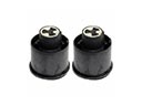 2006 Toyota Avalon Trailing Arm Bushing