×
ToyotaParts- Hello
- Login or Register
- Quick Links
- Live Chat
- Track Order
- Parts Availability
- RMA
- Help Center
- Contact Us
- Shop for
- Toyota Parts
- Scion Parts
My Garage
My Account
Cart
OEM 2005 Toyota Avalon Axle Shaft
Car Axle Shaft- Select Vehicle by Model
- Select Vehicle by VIN
Select Vehicle by Model
orMake
Model
Year
Select Vehicle by VIN
For the most accurate results, select vehicle by your VIN (Vehicle Identification Number).
4 Axle Shafts found

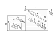
2005 Toyota Avalon Axle Assembly, Driver Side
Part Number: 43420-07070$436.46 MSRP: $639.64You Save: $203.18 (32%)Ships in 1-3 Business DaysProduct Specifications- Other Name: Shaft Assembly, Front Drive; CV Axle Assembly, Front Left; GSP Cv Axle; Axle Shaft; Shaft Assembly, Front Drive, Driver Side; CV Axle Assembly
- Position: Driver Side
- Part Name Code: 43420
- Item Weight: 18.40 Pounds
- Item Dimensions: 31.0 x 5.3 x 5.2 inches
- Condition: New
- Fitment Type: Direct Replacement
- SKU: 43420-07070
- Warranty: This genuine part is guaranteed by Toyota's factory warranty.

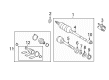
2005 Toyota Avalon Axle Assembly, Passenger Side
Part Number: 43410-07071$545.29 MSRP: $799.13You Save: $253.84 (32%)Product Specifications- Other Name: Shaft Assembly, Front Drive; CV Axle Assembly, Front Right; GSP Cv Axle; Axle Shaft; Shaft Assembly, Front Drive, Passenger Side; CV Axle Assembly
- Position: Passenger Side
- Replaces: 43410-07070
- Part Name Code: 43410
- Item Weight: 7.70 Pounds
- Item Dimensions: 28.9 x 7.5 x 6.4 inches
- Condition: New
- Fitment Type: Direct Replacement
- SKU: 43410-07071
- Warranty: This genuine part is guaranteed by Toyota's factory warranty.
 Product Specifications
- Other Name: Shaft Assembly, Outboard; CV Joint
- Position: Driver Side
- Item Weight: 5.60 Pounds
- Condition: New
- SKU: 43470-09D80
- Warranty: This genuine part is guaranteed by Toyota's factory warranty.
- Product Specifications
- Other Name: Shaft Assembly, Outboard; CV Joint
- Position: Passenger Side
- Condition: New
- SKU: 43460-09E50
- Warranty: This genuine part is guaranteed by Toyota's factory warranty.
2005 Toyota Avalon Axle Shaft
Looking for affordable OEM 2005 Toyota Avalon Axle Shaft? Explore our comprehensive catalogue of genuine 2005 Toyota Avalon Axle Shaft. All our parts are covered by the manufacturer's warranty. Plus, our straightforward return policy and speedy delivery service ensure an unparalleled shopping experience. We look forward to your visit!
2005 Toyota Avalon Axle Shaft Parts Q&A
- Q: How to service and repair the Axle Shaft on 2005 Toyota Avalon?A: The servicing process of the front drive shaft begins by removing the engine under cover LH followed by draining automatic transaxle fluid through drain plug removal. Then install a new gasket and reassemble drain plug with 49 Nm torque (500 kgf-cm, 36 ft. lbs.). You should release the staked part of the front axle hub LH nut by using Special Service Tool: 09930-00010 and hammering on it carefully until the nut becomes fully loose to avoid damaging the drive shaft screw. Lifting a 6 mm hexagon wrench onto the stud allows you to separate the front stabilizer link assembly LH by unfastening the nut first. First remove the bolt along with the clip holding the front LH speed sensor while taking precaution to avoid contamination on the component and then exploit Special Service Tool: 09628-62011 to free the tie rod end sub-assembly LH. Detach the front suspension arm sub-assembly lower No.1 LH by removing the bolt with two nuts and then proceed with separating the front axle assembly LH by first marking the front drive shaft assembly LH and axle hub and then using a plastic hammer to disassemble them while being cautious not to damage the drive shaft boot or speed sensor rotor. Use Special Service Tools 09520-01010 and 09520-24010 (09520-32040) to remove the front drive shaft assembly LH while avoiding dust cover damage along with boot and oil seal damage. Afterwards, remove the front drive shaft assembly RH by separating the bearing bracket hole snap ring together with its bolt. Use Special Service Tool 09608-16042 (09608-02021, 09608-02041) to fix the front axle hub sub-assembly LH because it will protect the hub bearing from damage during installation. Check the front drive shaft assembly LH for any abnormal movement while inspect the boots to determine whether they have suffered damage. Using pliers both the inboard joint boot clamp and front drive inner shaft outer LH shaft snap ring must be removed before separating the inboard joint boot from its assembly. Beginning the front drive inboard joint assembly LH removal requires marking both components after which detach the tripod joint from outboard joint shaft using a brass bar and hammer without striking the roller. Use appropriate Special Service Tools to remove the front drive shaft damper LH and the outboard joint boot before proceeding to maintain the front drive shaft dust cover LH, RH and the drive shaft bearing. The installation process includes adding a new bearing bracket hole snap ring and front drive shaft bearing which must be fully installed before adding the drive shaft dust cover and outboard joint boot. Packing material should be grease with 120-140 g amount for this specific outboard joint. Position the front drive shaft damper LH properly before installing the front axle inboard joint assembly LH. After alignment of matchmarks apply grease into the outboard joint shaft and boot at a rating of 190 to 210 g. First install the clamp before placing the front axle inboard joint boot. After that install the front drive inner shaft outer LH shaft snap ring. During front drive shaft assembly installation both LH and RH sides require ATF lubrication of the spline before placing the snap ring into its proper position. The procedure requires reinstallation of the LH front axle assembly together with the lower No.1 LH front suspension arm sub-assembly and LH tie rod end sub-assembly following torque specifications. Secure the speed sensor front LH with proper attachment before placing the front stabilizer link assembly LH. Install the front axle hub LH nut while performing staking procedures afterwards. The last procedures involve mounting the front wheel while you add automatic transaxle fluid to check liquid levels before setting the appropriate front wheel alignment following engine under cover LH installation to validate the ABS speed sensor signal.
Related 2005 Toyota Avalon Parts
 2005 Toyota Avalon Control Arm
 2005 Toyota Avalon Bump Stop
 2005 Toyota Avalon CV Boot
 2005 Toyota Avalon CV Joint
 2005 Toyota Avalon Coil Spring Insulator
 2005 Toyota Avalon Coil Springs
 2005 Toyota Avalon Lateral Link
 2005 Toyota Avalon Shock And Strut Mount
 2005 Toyota Avalon Strut Housing
 2005 Toyota Avalon Sway Bar Bracket
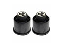 2005 Toyota Avalon Trailing Arm Bushing
 2005 Toyota Avalon Transfer Case Output Shaft Snap Ring