×
ToyotaParts- Hello
- Login or Register
- Quick Links
- Live Chat
- Track Order
- Parts Availability
- RMA
- Help Center
- Contact Us
- Shop for
- Toyota Parts
- Scion Parts
My Garage
My Account
Cart
OEM 2006 Scion xA Rack And Pinion
Steering Rack And Pinion- Select Vehicle by Model
- Select Vehicle by VIN
Select Vehicle by Model
orMake
Model
Year
Select Vehicle by VIN
For the most accurate results, select vehicle by your VIN (Vehicle Identification Number).
1 Rack And Pinion found

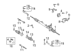
2006 Scion xA Steering Gear
Part Number: 44200-52340$610.09 MSRP: $894.08You Save: $283.99 (32%)Ships in 1-3 Business DaysProduct Specifications- Other Name: Rack and Pinion Assembly; Steering Gearbox; Gear Assembly; Steering Gear Assembly; Link Assembly, Power Steering
- Part Name Code: 44200
- Item Weight: 13.70 Pounds
- Item Dimensions: 50.2 x 10.4 x 6.6 inches
- Condition: New
- Fitment Type: Direct Replacement
- SKU: 44200-52340
- Warranty: This genuine part is guaranteed by Toyota's factory warranty.
2006 Scion xA Rack And Pinion
Looking for affordable OEM 2006 Scion xA Rack And Pinion? Explore our comprehensive catalogue of genuine 2006 Scion xA Rack And Pinion. All our parts are covered by the manufacturer's warranty. Plus, our straightforward return policy and speedy delivery service ensure an unparalleled shopping experience. We look forward to your visit!
2006 Scion xA Rack And Pinion Parts Q&A
- Q: How to disassemble the Rack And Pinion on 2006 Scion xA?A: Before removing the power steering link you must secure the steering link assembly using Special Service Tool: 09612-00012 and wrap it with vinyl tape beforehand. Begin by marking the tie rod end LH and rack end and proceed to loose the lock nut to extract the tie rod end and lock nut. Apply the same approach to remove the tie rod end on the right-hand side. The first step for boot removal involves taking out both rack and pinion boot clips followed by using a screwdriver to carefully separate the No. 2 rack and pinion boot clamp. Prevent damage to the boot while performing this step. First remove the boot clamp located at No. 1 then continue with the No. 2 and No. 1 rack and pinion boots' removal. The collection of Special Service Tool: 09922-10010 permits removal of the two rack ends before using the same tool to remove the spring cap lock nut so technicians can finish the procedure by using a 19 mm hexagon wrench to separate the rack guide spring cap. The technician needs to remove the rack guide spring followed by the rack guide spring spacer and the rack guide. The procedure for replacing the power steering control valve starts with marking the control valve and rack housing followed by bolt removal and extraction of the gasket together with the control valve and bolts. The needle nose pliers remove the hole snap ring to expose the cylinder end stopper which can then be pulled out. Special Service Tool: 09950-70010 (09951-07200) together with a press enable you to eliminate the power steering rack and rack bush from the system. Steer the rack bush from the rack and pinion and then employ Special Service Tool: 09612-24014 (09613-22011) to extract the rack bush oil seal followed by O-ring removal with a screwdriver. When replacing the rack and pinion piston ring you need to use a screwdriver to unfasten the ring and its accompanying O-ring without harming the ring grooves. Use Special Service Tool: 09950-60010 (09951-00200, 09951-00240, 09952-06010) and 09950-70010 (09951-07360) along with a press to remove the housing oil seal from the rack housing cautiously. A dial gauge should measure the power steering rack for runout, teeth wear and damage; replace the rack if the maximum deviation exceeds 0.1 mm (0.004 inch). Insert the tie rod end assembly into a vise then attach the nut to the stud bolt before moving the ball joint stud five times one after another and apply the torque wrench to continuously rotate the nut over 2 to 4 seconds each time to record the reading on turn five with a standard torque range from 0.8 Nm to 3.4 Nm (8.2 to 34.7 kgf-cm, 7.1 to 30.1 inch lbs.).
Related 2006 Scion xA Parts
 2006 Scion xA Power Steering Pump
 2006 Scion xA Drag Link
 2006 Scion xA Ignition Switch
 2006 Scion xA Power Steering Hose
 2006 Scion xA Power Steering Reservoir
 2006 Scion xA Rack and Pinion Boot
 2006 Scion xA Steering Angle Sensor
 2006 Scion xA Steering Column
 2006 Scion xA Steering Shaft
 2006 Scion xA Tie Rod End
 2006 Scion xA Wiper Switch