×
ToyotaParts- Hello
- Login or Register
- Quick Links
- Live Chat
- Track Order
- Parts Availability
- RMA
- Help Center
- Contact Us
- Shop for
- Toyota Parts
- Scion Parts
My Garage
My Account
Cart
OEM 2005 Toyota Sienna Power Steering Pump
Power Steering Pump Unit- Select Vehicle by Model
- Select Vehicle by VIN
Select Vehicle by Model
orMake
Model
Year
Select Vehicle by VIN
For the most accurate results, select vehicle by your VIN (Vehicle Identification Number).
1 Power Steering Pump found


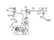
2005 Toyota Sienna Power Steering Pump
Part Number: 44310-08010$366.14 MSRP: $536.58You Save: $170.44 (32%)Product Specifications- Other Name: Pump Assembly, Vane
- Part Name Code: 44320
- Item Weight: 8.30 Pounds
- Item Dimensions: 7.7 x 5.8 x 4.8 inches
- Condition: New
- Fitment Type: Direct Replacement
- SKU: 44310-08010
- Warranty: This genuine part is guaranteed by Toyota's factory warranty.
2005 Toyota Sienna Power Steering Pump
Looking for affordable OEM 2005 Toyota Sienna Power Steering Pump? Explore our comprehensive catalogue of genuine 2005 Toyota Sienna Power Steering Pump. All our parts are covered by the manufacturer's warranty. Plus, our straightforward return policy and speedy delivery service ensure an unparalleled shopping experience. We look forward to your visit!
2005 Toyota Sienna Power Steering Pump Parts Q&A
- Q: How to service and repair the power steering pump on 2005 Toyota Sienna?A: Start the power steering pump servicing by taking out the front wheel RH and draining the power steering fluid. Start by taking out the front fender apron seal RH and following with the disconnect of oil reservoir to pump hose No.1 while preventing fluid from spraying onto the V belt. The power steering oil pressure switch requires removal after you disconnect its connector and unscrew the union bolt; replace the switch when it shows damage. Holding the pressure port union still with a 24 mm spanner notice allows removing the union bolt together with the gasket from the pressure feed tube assembly. First loosen the two bolts to detach the vane pump V belt before proceeding to remove the vane pump assembly through two bolt unscrewing. The power steering suction port union and its O-ring should be removed so you can take out the flow control valve and compression spring. Unscrew two bolts and nuts from the vane pump bracket rear before proceeding to remove its housing rear together with the gasket and two O-rings. Apply a screwdriver to remove the vane pump cam ring and snap ring following the removal of the vane pump side plate rear with wave washer. Start by removing 10 vane pump plates along with the vane pump rotor until all pieces including w/pulley shaft sub-assembly and pump bracket front are taken out. Take out the vane pump housing oil seal with caution to avoid destroying the bushing of the vane pump housing front part. Check the vane pump shaft oil clearance alongside the bushing until it matches acceptable parameters of 0.027 to 0.054 mm (0.00106 - 0.00213 inch) while staying beneath the maximum 0.07 mm (0.0028 inch) benchmark; implement new vane pump assemblies when necessary. Check the vane pump plates thickness to verify a minimum value of 1.397 to 1.403 mm (0.0550 to 0.05524 inch) while inspecting the vane pump rotor groove clearance with the vane pump plate using a maximum allowance of 0.03 mm (0.0012 inch). A new flow control valve installation is required when it does not deliver a smooth entry into the hole after coating it with power steering fluid. Check that the compression spring extends to 32.24 mm (1.2693 inch) free length while searching for damaged areas in the pressure port union that might lead to fluid leakage. A new vane pump housing oil seal receives power steering fluid coating before installation through the use of Special Service Tools: 09950-60010 (09951-00330), 09950-70010 (09951-07100) alongside a press for installation in the correct direction. The pump bracket front requires a torque of 44 Nm (449 kgf-cm, 32 ft. lbs.) before the w/pulley shaft sub-assembly can be inserted without damaging the vane pump housing oil seal lip. Assemble the vane pump cam ring and rotor by aligning them properly according to direction. Apply power steering fluid to cover ten plates of the vane pump and position them with round ends facing outside. Start by installing a new vane pump shaft snap ring through use of a snap ring expander and then put on the vane pump side plate rear while making sure the wave washer is correctly positioned and that the two new O-rings are coated with power steering fluid. Attach a new vane pump housing front gasket while checking its orientation before tightening the 4 bolts at 24 Nm (245 kgf-cm) or 18 ft. lbs. Use a service bolt with specified dimensions to check that the vane pump rotates without producing abnormal noises while measuring the torque which should not exceed 0.27 Nm (2.8 kgf-cm, 2.4 inch lbs.). Reinstall the vane pump bracket rear by securing the 2 bolts and nuts to 44 Nm (449 kgf-cm, 32 ft. lbs.) while faced correctly and implement the flow control valve along with the compression spring with proper orientation. Use steering fluid to lubricate a fresh O-ring that you should install on the pressure port union until it reaches 83 Nm (846 kgf-cm, 61 ft. lbs.) torque. Utilize power steering fluid to coat a new O-ring after which you should place it on the suction port union then tighten it to 13 Nm (133 kgf-cm, 10 ft. lbs.). Mount two bolts on the vane pump assembly before installing the vane pump V belt for tension adjustment and securing bolts A and B to 44 Nm (449 kgf-cm, 32 ft. lbs.). The pressure feed tube assembly needs installation while using a 24 mm spanner to tighten the pressure port union bolt with new gasket at 52 Nm (525 kgf-cm, 38 ft. lbs.) torque. The power steering oil pressure switch installation requires a torque setting of 21 Nm (214 kgf-cm, 15 ft. lbs.) while connecting the essential cable. This part of the repair concludes with connecting pump hose No.1 to the oil reservoir and installing the clip and the front fender apron seal RH followed by front wheel RH installation requiring a torque of 103 Nm (1,050 kgf-cm, 76 ft. lbs.). Post-installation check includes bleed testing and leak inspection of the power steering fluid system.
Related 2005 Toyota Sienna Parts
 2005 Toyota Sienna Rack And Pinion
 2005 Toyota Sienna Ignition Switch
 2005 Toyota Sienna Power Steering Hose
 2005 Toyota Sienna Power Steering Reservoir
 2005 Toyota Sienna Steering Angle Sensor
 2005 Toyota Sienna Rack and Pinion Boot
 2005 Toyota Sienna Drag Link
 2005 Toyota Sienna Shift Interlock Solenoid
 2005 Toyota Sienna Steering Column
 2005 Toyota Sienna Steering Gear Box
 2005 Toyota Sienna Tie Rod End
 2005 Toyota Sienna Wiper Switch