×
ToyotaParts- Hello
- Login or Register
- Quick Links
- Live Chat
- Track Order
- Parts Availability
- RMA
- Help Center
- Contact Us
- Shop for
- Toyota Parts
- Scion Parts
My Garage
My Account
Cart
OEM 2005 Toyota RAV4 Axle Shaft
Car Axle Shaft- Select Vehicle by Model
- Select Vehicle by VIN
Select Vehicle by Model
orMake
Model
Year
Select Vehicle by VIN
For the most accurate results, select vehicle by your VIN (Vehicle Identification Number).
18 Axle Shafts found

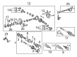
2005 Toyota RAV4 Axle Shafts, Rear Passenger Side
Part Number: 42370-49215$263.48 MSRP: $376.18You Save: $112.70 (30%)Ships in 1-3 Business DaysProduct Specifications- Other Name: Shaft Set, Rear Drive; Axle Shaft; CV Joint; Outer Joint
- Position: Rear Passenger Side
- Replaces: 42370-49075
- Condition: New
- SKU: 42370-49215
- Warranty: This genuine part is guaranteed by Toyota's factory warranty.
2005 Toyota RAV4 Axle Shafts, Rear Driver Side
Part Number: 42370-19205$263.48 MSRP: $376.18You Save: $112.70 (30%)Ships in 1-3 Business DaysProduct Specifications- Other Name: Shaft Set, Rear Drive; Axle Shaft; CV Joint; Outer Joint
- Position: Rear Driver Side
- Item Weight: 14.50 Pounds
- Item Dimensions: 33.7 x 6.3 x 5.8 inches
- Condition: New
- SKU: 42370-19205
- Warranty: This genuine part is guaranteed by Toyota's factory warranty.

2005 Toyota RAV4 Axle Assembly, Passenger Side
Part Number: 43410-42070$466.38 MSRP: $683.48You Save: $217.10 (32%)Ships in 1-3 Business DaysProduct Specifications- Other Name: Shaft Assembly, Front Drive; CV Axle Assembly, Front Right; GSP Cv Axle; Axle Shaft; Shaft Assembly, Front Drive, Passenger Side; CV Axle Assembly
- Position: Passenger Side
- Part Name Code: 43410
- Item Weight: 21.20 Pounds
- Item Dimensions: 44.1 x 5.7 x 5.6 inches
- Condition: New
- Fitment Type: Direct Replacement
- SKU: 43410-42070
- Warranty: This genuine part is guaranteed by Toyota's factory warranty.
2005 Toyota RAV4 Axle Assembly, Driver Side
Part Number: 43420-42130$419.44 MSRP: $614.70You Save: $195.26 (32%)Ships in 1-3 Business DaysProduct Specifications- Other Name: Shaft Assembly, Front Drive; CV Axle Assembly, Front Left; GSP Cv Axle; Axle Shaft; Shaft Assembly, Front Drive, Driver Side; CV Axle Assembly
- Position: Driver Side
- Part Name Code: 43420
- Item Weight: 18.70 Pounds
- Item Dimensions: 30.4 x 5.3 x 5.3 inches
- Condition: New
- Fitment Type: Direct Replacement
- SKU: 43420-42130
- Warranty: This genuine part is guaranteed by Toyota's factory warranty.

2005 Toyota RAV4 Axle Assembly, Passenger Side
Part Number: 42330-42041$415.66 MSRP: $609.15You Save: $193.49 (32%)Ships in 1-3 Business DaysProduct Specifications- Other Name: Shaft Assembly, Rear Drive; CV Axle Assembly, Rear Right; CV Axle Assembly; GSP Cv Axle; Axle Shaft
- Position: Passenger Side
- Replaces: 42330-42040
- Part Name Code: 42330
- Item Weight: 15.50 Pounds
- Item Dimensions: 28.4 x 8.7 x 7.4 inches
- Condition: New
- SKU: 42330-42041
- Warranty: This genuine part is guaranteed by Toyota's factory warranty.
2005 Toyota RAV4 Axle Assembly, Driver Side
Part Number: 43420-42060$395.80 MSRP: $580.05You Save: $184.25 (32%)Ships in 1-3 Business DaysProduct Specifications- Other Name: Shaft Assembly, Front Drive; CV Axle Assembly, Front Left; GSP Cv Axle; Axle Shaft; Shaft Assembly, Front Drive, Driver Side; CV Axle Assembly
- Position: Driver Side
- Part Name Code: 43420
- Item Weight: 17.50 Pounds
- Item Dimensions: 31.3 x 5.2 x 5.1 inches
- Condition: New
- Fitment Type: Direct Replacement
- SKU: 43420-42060
- Warranty: This genuine part is guaranteed by Toyota's factory warranty.
2005 Toyota RAV4 Axle Assembly, Driver Side
Part Number: 42340-12052$387.49 MSRP: $567.87You Save: $180.38 (32%)Ships in 1-3 Business DaysProduct Specifications- Other Name: Shaft Assembly, Rear Drive; CV Axle Assembly, Rear Left; CV Axle Assembly; GSP Cv Axle; Axle Shaft
- Position: Driver Side
- Replaces: 42340-12051
- Part Name Code: 42340B
- Item Weight: 15.30 Pounds
- Item Dimensions: 27.9 x 8.6 x 7.5 inches
- Condition: New
- SKU: 42340-12052
- Warranty: This genuine part is guaranteed by Toyota's factory warranty.
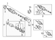
2005 Toyota RAV4 Axle Shafts, Passenger Side
Part Number: 42370-49085$279.88 MSRP: $399.60You Save: $119.72 (30%)Ships in 1-3 Business DaysProduct Specifications- Other Name: Shaft Assembly, Rear Drive; Axle Shaft; CV Joint; Outer Joint; Shaft Assembly, Rear Drive Outboard Joint, Passenger Side
- Position: Passenger Side
- Part Name Code: 42370A
- Item Weight: 13.80 Pounds
- Item Dimensions: 33.0 x 6.5 x 5.7 inches
- Condition: New
- Fitment Type: Direct Replacement
- SKU: 42370-49085
- Warranty: This genuine part is guaranteed by Toyota's factory warranty.
2005 Toyota RAV4 Axle Shafts, Driver Side
Part Number: 42370-49105$274.74 MSRP: $392.26You Save: $117.52 (30%)Ships in 1-3 Business DaysProduct Specifications- Other Name: Shaft Assembly, Rear Drive; Axle Shaft; CV Joint; Outer Joint; Shaft Assembly, Rear Drive Outboard Joint, Driver Side
- Position: Driver Side
- Part Name Code: 42380
- Item Weight: 13.80 Pounds
- Item Dimensions: 33.7 x 6.2 x 5.6 inches
- Condition: New
- Fitment Type: Direct Replacement
- SKU: 42370-49105
- Warranty: This genuine part is guaranteed by Toyota's factory warranty.
2005 Toyota RAV4 Axle Assembly, Passenger Side
Part Number: 43410-42090$452.10 MSRP: $662.57You Save: $210.47 (32%)Ships in 1-3 Business DaysProduct Specifications- Other Name: Shaft Assembly, Front Drive; CV Axle Assembly; GSP Cv Axle; Axle Shaft; Shaft Assembly, Front Drive, Passenger Side
- Position: Passenger Side
- Part Name Code: 43410
- Item Weight: 24.40 Pounds
- Item Dimensions: 43.3 x 5.5 x 5.4 inches
- Condition: New
- Fitment Type: Direct Replacement
- SKU: 43410-42090
- Warranty: This genuine part is guaranteed by Toyota's factory warranty.
2005 Toyota RAV4 Axle Assembly, Driver Side
Part Number: 43420-42080$417.74 MSRP: $612.20You Save: $194.46 (32%)Ships in 1-3 Business DaysProduct Specifications- Other Name: Shaft Assembly, Front Drive; CV Axle Assembly; GSP Cv Axle; Axle Shaft; Shaft Assembly, Front Drive, Driver Side
- Position: Driver Side
- Part Name Code: 43420
- Item Weight: 14.00 Pounds
- Item Dimensions: 29.5 x 7.2 x 6.4 inches
- Condition: New
- Fitment Type: Direct Replacement
- SKU: 43420-42080
- Warranty: This genuine part is guaranteed by Toyota's factory warranty.
2005 Toyota RAV4 Axle Assembly, Driver Side
Part Number: 43420-42070$417.74 MSRP: $612.20You Save: $194.46 (32%)Ships in 1-3 Business DaysProduct Specifications- Other Name: Shaft Assembly, Front Drive; CV Axle Assembly; GSP Cv Axle; Axle Shaft; Shaft Assembly, Front Drive, Driver Side
- Manufacturer Note: W(ABS)
- Position: Driver Side
- Part Name Code: 43420
- Item Weight: 14.10 Pounds
- Item Dimensions: 30.1 x 7.5 x 6.4 inches
- Condition: New
- Fitment Type: Direct Replacement
- SKU: 43420-42070
- Warranty: This genuine part is guaranteed by Toyota's factory warranty.
2005 Toyota RAV4 Axle Assembly, Driver Side
Part Number: 43420-42120$419.71 MSRP: $615.09You Save: $195.38 (32%)Ships in 1-3 Business DaysProduct Specifications- Other Name: Shaft Assembly, Front Drive; CV Axle Assembly, Front Left; GSP Cv Axle; Axle Shaft; Shaft Assembly, Front Drive, Driver Side; CV Axle Assembly
- Manufacturer Note: W(ABS)
- Position: Driver Side
- Part Name Code: 43420
- Item Weight: 17.30 Pounds
- Item Dimensions: 30.4 x 5.2 x 5.2 inches
- Condition: New
- Fitment Type: Direct Replacement
- SKU: 43420-42120
- Warranty: This genuine part is guaranteed by Toyota's factory warranty.
2005 Toyota RAV4 Axle Assembly, Driver Side
Part Number: 42340-12062$389.75 MSRP: $571.17You Save: $181.42 (32%)Ships in 1-3 Business DaysProduct Specifications- Other Name: Shaft Assembly, Rear Drive; CV Axle Assembly, Rear Left; GSP Cv Axle; Axle Shaft; Shaft Assembly, Rear Drive, Driver Side; CV Axle Assembly
- Manufacturer Note: W(ABS)
- Position: Driver Side
- Replaces: 42340-12061
- Part Name Code: 42340B
- Item Weight: 15.80 Pounds
- Item Dimensions: 27.6 x 8.4 x 7.5 inches
- Condition: New
- Fitment Type: Direct Replacement
- SKU: 42340-12062
- Warranty: This genuine part is guaranteed by Toyota's factory warranty.
- Product Specifications
- Other Name: Shaft Assembly, Front Drive; CV Axle Assembly; GSP Cv Axle; Axle Shaft; Shaft Assembly, Front Drive, Passenger Side
- Manufacturer Note: W(ABS)
- Position: Passenger Side
- Part Name Code: 43410
- Item Weight: 22.20 Pounds
- Item Dimensions: 42.4 x 5.5 x 5.6 inches
- Condition: New
- Fitment Type: Direct Replacement
- SKU: 43410-42080
- Warranty: This genuine part is guaranteed by Toyota's factory warranty.
- Product Specifications
- Other Name: Shaft Assembly, Front Drive; CV Axle Assembly, Front Left; GSP Cv Axle; Axle Shaft; Shaft Assembly, Front Drive, Driver Side; CV Axle Assembly
- Manufacturer Note: W(ABS)
- Position: Driver Side
- Part Name Code: 43420
- Item Weight: 17.20 Pounds
- Item Dimensions: 29.8 x 5.1 x 5.2 inches
- Condition: New
- Fitment Type: Direct Replacement
- SKU: 43420-42050
- Warranty: This genuine part is guaranteed by Toyota's factory warranty.
- Product Specifications
- Other Name: Shaft Assembly, Front Drive; CV Axle Assembly, Front Right; GSP Cv Axle; Axle Shaft; Shaft Assembly, Front Drive, Passenger Side; CV Axle Assembly
- Manufacturer Note: W(ABS)
- Position: Passenger Side
- Part Name Code: 43410
- Item Weight: 20.60 Pounds
- Item Dimensions: 43.3 x 5.7 x 5.5 inches
- Condition: New
- Fitment Type: Direct Replacement
- SKU: 43410-42060
- Warranty: This genuine part is guaranteed by Toyota's factory warranty.
- Product Specifications
- Other Name: Shaft Assembly, Rear Drive; CV Axle Assembly, Rear Right; GSP Cv Axle; Axle Shaft; Shaft Assembly, Rear Drive, Passenger Side; CV Axle Assembly
- Manufacturer Note: W(ABS)
- Position: Passenger Side
- Replaces: 42330-42030
- Part Name Code: 42330
- Item Weight: 15.50 Pounds
- Item Dimensions: 28.4 x 8.6 x 7.4 inches
- Condition: New
- Fitment Type: Direct Replacement
- SKU: 42330-42031
- Warranty: This genuine part is guaranteed by Toyota's factory warranty.
2005 Toyota RAV4 Axle Shaft
Looking for affordable OEM 2005 Toyota RAV4 Axle Shaft? Explore our comprehensive catalogue of genuine 2005 Toyota RAV4 Axle Shaft. All our parts are covered by the manufacturer's warranty. Plus, our straightforward return policy and speedy delivery service ensure an unparalleled shopping experience. We look forward to your visit!
2005 Toyota RAV4 Axle Shaft Parts Q&A
- Q: How to remove and install the axle shaft on 2005 Toyota RAV4?A: The removal or installation of axle shafts starts with hub bearing support through Special Service Tool: 09608-16042 (09608-02021, 09608-02041) when the vehicle weight needs support. The procedure for vehicles with ABS requires you to preserve the ABS speed sensor rotor serrations by being cautious when disconnecting the drive shaft from the axle hub. First uninstall the front wheel before tightening it to 103 Nm torque (1,050 kgf-cm and 76 ft. lbs. torque). The vehicle requires a drain of gear oil (M/T) and ATF (A/T) oil as well as transfer oil drainage for 4WD systems. Use Special Service Tool: 09930-00010 and apply a hammer to unstake the lock nut before removing it at a braking torque of 216 Nm (2,200 kgf-cm, 159 ft. lbs.). Disconnect the lower suspension arm by unscrewing its bolt and two nuts to a torque of 128 Nm (1,310 kgf-cm, 94 ft. lbs.). A plastic hammer can be used to separate the drive shaft from the axle hub while protecting the ABS speed sensor rotor. The RH drive shaft in 2WD requires removal of its two bolts along with the drive shaft at 64 Nm (650 kgf-cm, 47 ft. lbs.) torque while applying grease to the oil seal lip with MP during assembly. To remove other drive shafts you must employ Special Service Tools 09520-01010 and 09520-24010 (09520-32040) before using a screwdriver to remove the snap ring. When installing the snap ring position it with the opening at the bottom while checking that it touches the pinion shaft through sound detection and feeling 2 - 3 mm (0.08 - 0.12 inch) free axial movement afterwards and that the drive shaft does not remove easily by hand contact. The installation procedure needs to follow the opposite steps of removal and after installation you should inspect both ABS speed sensor signals and front wheel alignment.
Related 2005 Toyota RAV4 Parts
 2005 Toyota RAV4 Control Arm
 2005 Toyota RAV4 Control Arm Bushing
 2005 Toyota RAV4 Axle Beam Mount
 2005 Toyota RAV4 Bump Stop
 2005 Toyota RAV4 CV Boot
 2005 Toyota RAV4 Coil Spring Insulator
 2005 Toyota RAV4 Coil Springs
 2005 Toyota RAV4 Crossmember Bushing
 2005 Toyota RAV4 Differential Mount
 2005 Toyota RAV4 Shock Absorber
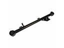 2005 Toyota RAV4 Trailing Arm
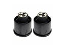 2005 Toyota RAV4 Trailing Arm Bushing